3D printer controller
Paired with a RAMPS 1.4 shield and stepper drivers, the Mega runs Marlin firmware to control stepper motors, heaters, thermistors, and endstops. Its pin count and memory are what make this classic build possible.
An ATmega2560-based Arduino board with 54 digital I/O pins and 256 KB of flash for projects that outgrow the Uno.
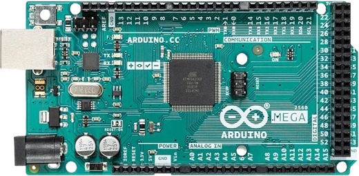
The Arduino Mega 2560 is a microcontroller board built around Microchip's ATmega2560 running at 16 MHz. It exposes 54 digital I/O pins, 16 analog inputs, 256 KB of flash memory, 8 KB of SRAM, and 4 KB of EEPROM, giving it far more room for pins, code, and variables than the Uno. This makes it the default choice when a build needs to talk to dozens of sensors, drivers, or displays at once.
The board runs its logic at 5V and offers four hardware UARTs (serial ports), an SPI bus on pins D50 to D53, and an I2C bus on D20 (SDA) and D21 (SCL). Fifteen of the digital pins can output PWM. A separate ATmega16U2 handles the USB connection by acting as a USB-to-serial converter, so the board shows up as a COM port for uploading sketches and printing to the Serial Monitor.
The Mega keeps the Uno header footprint at one end, so most Uno shields still fit, while adding two long banks of extra headers along the board for large wiring harnesses. Makers reach for it in 3D printers, CNC controllers, home automation hubs, and any project where the pin count or memory of a smaller board runs out.
| Pin | Function | Type |
|---|---|---|
D0 D0 (RX0) | UART RX · Digital | Bidirectional (GPIO) |
D1 D1 (TX0) | UART TX · Digital | Bidirectional (GPIO) |
D2 D2 (PWM) | PWM · Digital | Bidirectional (GPIO) |
D3 D3 (PWM) | PWM · Digital | Bidirectional (GPIO) |
D4 D4 (PWM) | PWM · Digital | Bidirectional (GPIO) |
D5 D5 (PWM) | PWM · Digital | Bidirectional (GPIO) |
D6 D6 (PWM) | PWM · Digital | Bidirectional (GPIO) |
D7 D7 (PWM) | PWM · Digital | Bidirectional (GPIO) |
D8 D8 (PWM) | PWM · Digital | Bidirectional (GPIO) |
D9 D9 (PWM) | PWM · Digital | Bidirectional (GPIO) |
D10 D10 (PWM) | PWM · Digital | Bidirectional (GPIO) |
D11 D11 (PWM) | PWM · Digital | Bidirectional (GPIO) |
D12 D12 (PWM) | PWM · Digital | Bidirectional (GPIO) |
D13 D13 (LED) | PWM · Digital | Bidirectional (GPIO) |
D14 D14 (TX3) | UART TX3 · Digital | Bidirectional (GPIO) |
D15 D15 (RX3) | UART RX3 · Digital | Bidirectional (GPIO) |
D16 D16 (TX2) | UART TX2 · Digital | Bidirectional (GPIO) |
D17 D17 (RX2) | UART RX2 · Digital | Bidirectional (GPIO) |
D18 D18 (TX1) | UART TX1 · Digital | Bidirectional (GPIO) |
D19 D19 (RX1) | UART RX1 · Digital | Bidirectional (GPIO) |
D20 D20 (SDA) | I²C SDA · Digital | Bidirectional (GPIO) |
D21 D21 (SCL) | I²C SCL · Digital | Bidirectional (GPIO) |
D22 D22 | Digital | Bidirectional (GPIO) |
D23 D23 | Digital | Bidirectional (GPIO) |
D24 D24 | Digital | Bidirectional (GPIO) |
D25 D25 | Digital | Bidirectional (GPIO) |
D26 D26 | Digital | Bidirectional (GPIO) |
D27 D27 | Digital | Bidirectional (GPIO) |
D28 D28 | Digital | Bidirectional (GPIO) |
D29 D29 | Digital | Bidirectional (GPIO) |
D30 D30 | Digital | Bidirectional (GPIO) |
D31 D31 | Digital | Bidirectional (GPIO) |
D32 D32 | Digital | Bidirectional (GPIO) |
D33 D33 | Digital | Bidirectional (GPIO) |
D34 D34 | Digital | Bidirectional (GPIO) |
D35 D35 | Digital | Bidirectional (GPIO) |
D36 D36 | Digital | Bidirectional (GPIO) |
D37 D37 | Digital | Bidirectional (GPIO) |
D38 D38 | Digital | Bidirectional (GPIO) |
D39 D39 | Digital | Bidirectional (GPIO) |
D40 D40 | Digital | Bidirectional (GPIO) |
D41 D41 | Digital | Bidirectional (GPIO) |
D42 D42 | Digital | Bidirectional (GPIO) |
D43 D43 | Digital | Bidirectional (GPIO) |
D44 D44 (PWM) | PWM · Digital | Bidirectional (GPIO) |
D45 D45 (PWM) | PWM · Digital | Bidirectional (GPIO) |
D46 D46 (PWM) | PWM · Digital | Bidirectional (GPIO) |
D47 D47 | Digital | Bidirectional (GPIO) |
D48 D48 | Digital | Bidirectional (GPIO) |
D49 D49 | Digital | Bidirectional (GPIO) |
D50 D50 (MISO) | SPI MISO · Digital | Bidirectional (GPIO) |
D51 D51 (MOSI) | SPI MOSI · Digital | Bidirectional (GPIO) |
D52 D52 (SCK) | SPI SCK · Digital | Bidirectional (GPIO) |
D53 D53 (SS) | SPI SS · Digital | Bidirectional (GPIO) |
A0 A0 | Analog ADC0 · Digital | Bidirectional (GPIO) |
A1 A1 | Analog ADC1 · Digital | Bidirectional (GPIO) |
A2 A2 | Analog ADC2 · Digital | Bidirectional (GPIO) |
A3 A3 | Analog ADC3 · Digital | Bidirectional (GPIO) |
A4 A4 | Analog ADC4 · Digital | Bidirectional (GPIO) |
A5 A5 | Analog ADC5 · Digital | Bidirectional (GPIO) |
A6 A6 | Analog ADC6 · Digital | Bidirectional (GPIO) |
A7 A7 | Analog ADC7 · Digital | Bidirectional (GPIO) |
A8 A8 | Analog ADC8 · Digital | Bidirectional (GPIO) |
A9 A9 | Analog ADC9 · Digital | Bidirectional (GPIO) |
A10 A10 | Analog ADC10 · Digital | Bidirectional (GPIO) |
A11 A11 | Analog ADC11 · Digital | Bidirectional (GPIO) |
A12 A12 | Analog ADC12 · Digital | Bidirectional (GPIO) |
A13 A13 | Analog ADC13 · Digital | Bidirectional (GPIO) |
A14 A14 | Analog ADC14 · Digital | Bidirectional (GPIO) |
A15 A15 | Analog ADC15 · Digital | Bidirectional (GPIO) |
SDA SDA (D20) | I²C SDA · Digital | Bidirectional (GPIO) |
SCL SCL (D21) | I²C SCL · Digital | Bidirectional (GPIO) |
5V 5V | Power | Power out |
5V2 5V | Power | Power out |
3V3 3.3V | Power | Power out |
VIN VIN | Power | Power in |
GND GND | Power | Power in |
GND2 GND | Power | Power in |
GND3 GND | Power | Power in |
RESET RESET | Digital | Digital input |
IOREF IOREF | Power | Power out |
AREF AREF | Digital input | Digital input |
Verified from the Tinkered component library · Arduino.
The Arduino Mega 2560 is fully simulated in Tinkered. Wire it into a circuit, write your firmware, and read real values back with no physical hardware. Test your logic before you touch a breadboard.
Open it in the simulatorOn the Mega, I2C is on D20 (SDA) and D21 (SCL), not A4/A5, and SPI (MOSI, MISO, SCK) is on D51, D50, D52 with SS on D53. Libraries and wiring copied from an Uno will not talk to the right pins unless you remap them.
The Mega's outputs swing to 5V. Wiring a 3.3V sensor, SD card, or radio directly to a Mega output pin can damage it. Use a logic level shifter on the lines running from the Mega into the 3.3V device.
With a roughly 20 mA per-pin recommendation and 40 mA absolute limit, a pin cannot power a DC motor, a relay coil, or a strip of LEDs. Overloading pins can damage the ATmega2560. Switch those loads with a transistor, MOSFET, or dedicated driver.
Supplying less than 7V leaves the regulator unable to hold 5V and makes the board unstable, while more than 12V makes the regulator run hot and risks damage. Keep VIN in the 7-12V range, or feed a clean regulated 5V into the 5V pin instead.
The bootloader occupies about 8 KB of the 256 KB flash, so usable program space is closer to 248 KB. Budget for this on large sketches so uploads do not fail near the memory ceiling.
Paired with a RAMPS 1.4 shield and stepper drivers, the Mega runs Marlin firmware to control stepper motors, heaters, thermistors, and endstops. Its pin count and memory are what make this classic build possible.
The abundance of digital pins and hardware interrupts lets the Mega drive multi-axis stepper motion, limit switches, and spindle or laser control for a desktop CNC or engraver.
With four UARTs, I2C, SPI, and dozens of free pins, the Mega coordinates banks of relays, temperature and motion sensors, and status displays for a whole-room control panel.
The extra RAM and pin count let the Mega drive long strips or matrices of addressable LEDs and animate them from multiple input buttons or sensors at once.
Using SPI for an SD card and I2C plus the 16 analog inputs for sensors, the Mega samples many channels and timestamps readings to a file, ideal for weather or environmental monitoring.
The wide array of analog inputs and digital pins reads many potentiometers, faders, and buttons, and one of the hardware serial ports carries MIDI out to a computer or synth.
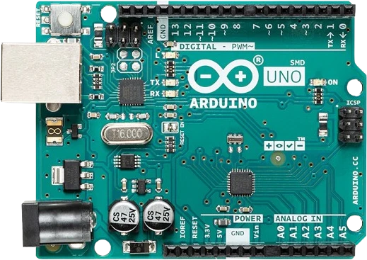
arduino-unoATmega328P · 5V logic
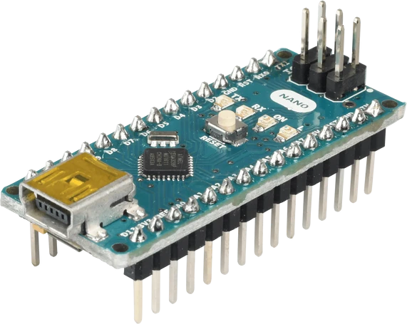
arduino-nano-v3ATmega328P · Compact format
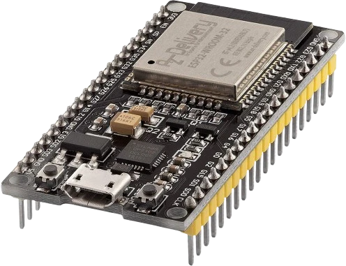
esp32-devkitWi-Fi + Bluetooth
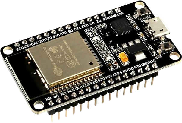
esp32-devkit-v1DOIT · 30-pin
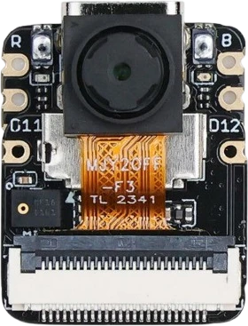
xiao-esp32-s3-senseCompact AI + wireless
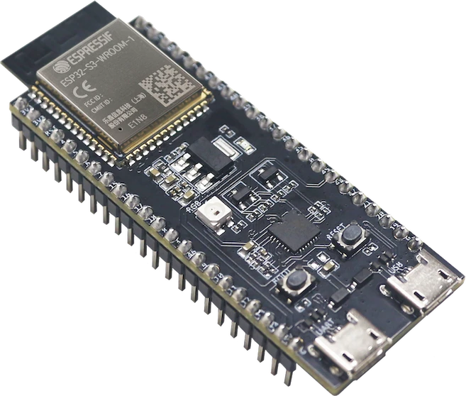
esp32-s3-wroom-freenoveFreenove development board
Drop the Arduino Mega 2560 into a circuit, write firmware, and simulate it in your browser, then deploy to real hardware. All in one editable Tinkered project.