Blink and first sketches
The classic starting point: toggle the onboard LED on pin 13, then wire external LEDs and buttons to learn digital output, input, and timing.
The classic ATmega328P development board with 5V logic and a 16 MHz clock, the standard entry point for learning Arduino.
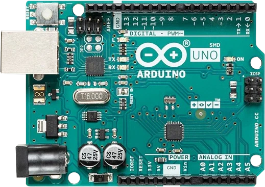
The Arduino Uno is an open-source microcontroller board built around Microchip's 8-bit ATmega328P running at 16 MHz. It exposes 14 digital I/O pins (6 capable of PWM) and 6 analog inputs on a header layout that has become the de facto standard, so the vast majority of shields and tutorials are designed to fit it. All logic operates at 5V.
A second chip, the ATmega16U2, handles USB-to-serial conversion, letting the board appear as a virtual COM port over its USB Type-B connector for both sketch uploads and serial communication. The main ATmega328P ships with the Arduino bootloader and, because it sits in a socket rather than being soldered, it can be swapped out if it is ever damaged. The board carries 32 KB of flash (about 0.5 KB used by the bootloader), 2 KB of SRAM, and 1 KB of EEPROM for non-volatile storage.
Makers use the Uno as a general-purpose controller: read sensors on the analog and digital pins, drive LEDs, displays, and motors (through suitable drivers), talk to peripherals over I2C, SPI, or UART, and react in real time from code written in the Arduino IDE. Its forgiving 5V I/O, large community, and abundant example code make it the usual first board for prototyping and education.
| Pin | Function | Type |
|---|---|---|
D0 D0 (RX) | UART RX · Digital | Bidirectional (GPIO) |
D1 D1 (TX) | UART TX · Digital | Bidirectional (GPIO) |
D2 D2 | Digital | Bidirectional (GPIO) |
D3 D3 (PWM) | PWM · Digital | Bidirectional (GPIO) |
D4 D4 | Digital | Bidirectional (GPIO) |
D5 D5 (PWM) | PWM · Digital | Bidirectional (GPIO) |
D6 D6 (PWM) | PWM · Digital | Bidirectional (GPIO) |
D7 D7 | Digital | Bidirectional (GPIO) |
D8 D8 | Digital | Bidirectional (GPIO) |
D9 D9 (PWM) | PWM · Digital | Bidirectional (GPIO) |
D10 D10 (PWM) | PWM · SPI SS · Digital | Bidirectional (GPIO) |
D11 D11 (PWM) | PWM · SPI MOSI · Digital | Bidirectional (GPIO) |
D12 D12 | SPI MISO · Digital | Bidirectional (GPIO) |
D13 D13 (LED) | SPI SCK · Digital | Bidirectional (GPIO) |
SDA SDA (A4) | I²C SDA · Digital | Bidirectional (GPIO) |
SCL SCL (A5) | I²C SCL · Digital | Bidirectional (GPIO) |
A0 A0 | Analog · Digital | Bidirectional (GPIO) |
A1 A1 | Analog · Digital | Bidirectional (GPIO) |
A2 A2 | Analog · Digital | Bidirectional (GPIO) |
A3 A3 | Analog · Digital | Bidirectional (GPIO) |
A4 A4 (SDA) | Analog · I²C SDA · Digital | Bidirectional (GPIO) |
A5 A5 (SCL) | Analog · I²C SCL · Digital | Bidirectional (GPIO) |
5V 5V | Power | Power out |
3V3 3.3V | Power | Power out |
VIN VIN | Power | Power in |
GND GND | Power | Power in |
GND2 GND | Power | Power in |
GND3 GND | Power | Power in |
RESET RESET | Digital | Digital input |
IOREF IOREF | Power | Power out |
AREF AREF | Digital input | Digital input |
NC NC | No connect | No connect |
Verified from the Tinkered component library · Arduino.
The Arduino Uno is fully simulated in Tinkered. Wire it into a circuit, write your firmware, and read real values back with no physical hardware. Test your logic before you touch a breadboard.
Open it in the simulatorEach I/O pin sources only about 20mA. Connecting a DC motor, relay coil, or high-power load directly can exceed that limit and damage the pin or the microcontroller. Use a transistor, MOSFET, motor driver, or relay module with its own supply.
The Uno runs at 5V logic. Its 5V outputs can over-voltage a 3.3V-only sensor or module, and some 3.3V devices are not 5V tolerant on their inputs. Add level shifting where the datasheet calls for it.
The onboard regulator needs headroom. Supplying 5V or less into VIN/the jack leaves the 5V rail sagging and the board unstable. Use 7-12V there, or feed a clean regulated 5V into the 5V pin instead.
Pins 0 and 1 are the hardware UART shared with the USB-to-serial chip. Devices connected there interfere with uploading sketches and with Serial.print debugging. Move them to other pins or disconnect during upload.
When a sensor, module, or motor runs off a separate power supply, its ground must connect to an Arduino GND pin. Without a shared reference, signal readings are erratic or the circuit does not work at all.
The classic starting point: toggle the onboard LED on pin 13, then wire external LEDs and buttons to learn digital output, input, and timing.
Read a DHT22 or similar sensor and show live temperature and humidity on a 16x2 LCD or an OLED display over I2C.
Use an HC-SR04 to measure distance and trigger LEDs or a buzzer as an object gets closer, a common intro to timing pulses in code.
Drive one or more SG90 servos from PWM pins, optionally steered by potentiometers, to build a pan-tilt mount or a small robotic arm.
Combine a motor driver, distance or IR sensors, and the Uno's logic to build a small autonomous rover, a popular first robotics build.
Sample analog sensors on a timer and record readings to EEPROM or an SD card module over SPI for later review.
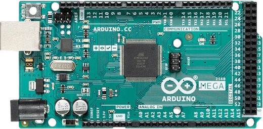
arduino-megaATmega2560 · Expanded I/O
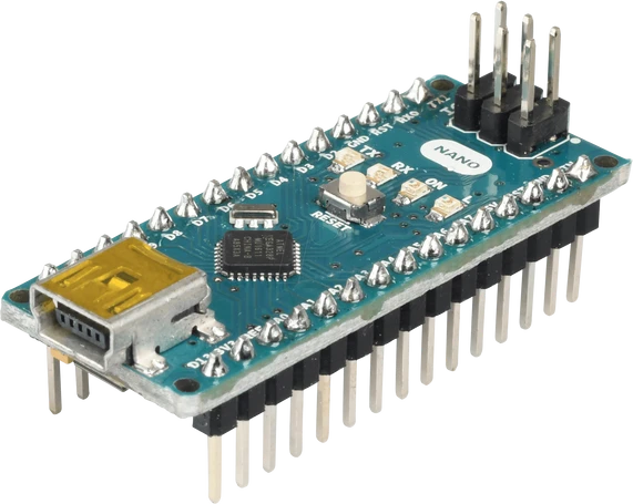
arduino-nano-v3ATmega328P · Compact format
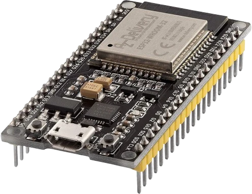
esp32-devkitWi-Fi + Bluetooth
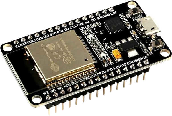
esp32-devkit-v1DOIT · 30-pin
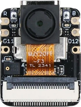
xiao-esp32-s3-senseCompact AI + wireless
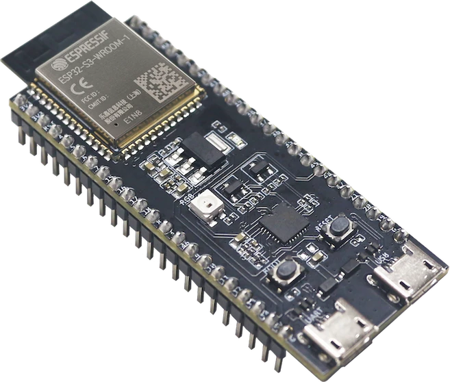
esp32-s3-wroom-freenoveFreenove development board
Drop the Arduino Uno into a circuit, write firmware, and simulate it in your browser, then deploy to real hardware. All in one editable Tinkered project.