Breadboard (Full-size)
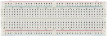
A full-size solderless breadboard with 830 tie points for building and reworking circuits without soldering.
What is the Breadboard (Full-size)?
A breadboard is a reusable base for building electronic circuits without soldering. You push component leads and jumper wires into its spring-clip holes, called tie points, and the clips both hold the parts and connect them electrically. That means a circuit can be assembled, changed, and taken apart in seconds, which makes breadboards the standard way to prototype before committing to a soldered board.
The holes sit on a 0.1 inch (2.54 mm) grid, the same pitch as through-hole ICs and standard 0.1 inch headers. In the main building area the holes are connected in short columns of five: the five holes in a column are joined together, while each column stays separate from its neighbors. A channel runs down the center so a DIP chip can straddle it, landing each row of pins on its own isolated column.
The long strips along both edges are the power rails, or bus strips. Each rail runs the length of the board and is used to distribute one net, typically power or ground, wherever the circuit needs it. On many full-size boards each rail is split in the middle, so the two halves have to be jumpered together when you need that rail along the whole length.
Specifications
- Tie points
- 830 totalStandard full-size breadboard
- Hole pitch
- 0.1 in (2.54 mm)Standard full-size breadboard
- Terminal strips
- Two halves, columns of 5 connected holesStandard full-size breadboard
- Power rails
- 4 bus strips (2 per side), usually split mid-lengthStandard full-size breadboard
- Center channel
- Isolates the two halves so DIP ICs straddle itStandard full-size breadboard
- Typical size
- about 165 × 55 mmStandard full-size breadboard
Every specification is cited to its source.
Common Breadboard (Full-size) mistakes
Forgetting the center channel
The two terminal-strip halves are not connected across the middle channel. A DIP IC is meant to straddle it so each pin sits on its own column. If you place parts expecting them to connect across the channel, that connection is never made.
Assuming the power rails run the full length
On many full-size boards each power rail is broken in the middle. If your circuit needs power or ground along the whole board, add a jumper to bridge the two halves of the rail.
Using wire that is too thick or stranded
Thick or stranded wire and heavy component legs can spread or damage the spring clips, leaving loose, intermittent contacts. Use solid-core jumper wire (typically 22 AWG) and keep component leads clean and straight.
Running high current or mains voltage through it
A breadboard is for low-voltage, low-current prototyping. The clips have real contact resistance and are not rated for high current or mains voltage, so keep them for logic and small-signal work rather than power delivery.
More breadboards
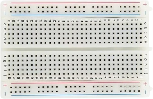
Build with the Breadboard (Full-size).
Drop the Breadboard (Full-size) into a circuit, write firmware, and simulate it in your browser, then deploy to real hardware. All in one editable Tinkered project.