100nF Ceramic Capacitor
A 100nF (0.1uF) non-polarized ceramic capacitor, the standard decoupling and bypass part for keeping IC power rails quiet.
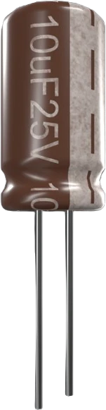
What is the 100nF Ceramic Capacitor?
The 100nF ceramic capacitor stores 0.1uF, equal to 100,000pF, and is almost always printed with the three-digit code 104 (10 followed by four zeros in picofarads). It is a two-terminal, non-polarized part built from a ceramic dielectric, so it can be inserted either way around. The version modeled here is rated to 50V, comfortably above the 3.3V and 5V rails used in most Arduino and microcontroller projects.
This value is the workhorse decoupling (bypass) capacitor. Placed right next to a chip's power pin, it acts as a tiny local charge reservoir: when the IC draws a fast burst of current, the capacitor supplies it locally before the regulator or bulk capacitor can respond, and it shunts high-frequency switching noise to ground. Its small size keeps parasitic inductance low, which is what makes it effective at the megahertz frequencies where larger electrolytics fall short.
Dielectric type matters for the details. General-purpose 100nF caps use Class 2 ceramics such as X7R or Y5V, which pack a lot of capacitance into a small body but lose effective capacitance under applied DC bias and temperature swings. For timing or filtering where precision matters, a C0G/NP0 (Class 1) 100nF is far more stable but physically larger. For plain decoupling, any 50V ceramic 104 is fine.
Specifications
- Dimensions
- 4 × 3 × 2 mm
Verified from the Tinkered component library.
Circuit requirements
- Non-polarized: unlike electrolytic capacitors, it has no plus or minus lead and can be connected in either orientation.
- For decoupling, wire it directly between the IC's VCC/VDD pin and GND, as physically close to the pin as possible (ideally within a few millimeters) to keep trace inductance low.
- Keep the actual DC operating voltage well below the 50V rating; Class 2 ceramics (X7R, Y5V) shed a meaningful fraction of their rated capacitance as DC bias approaches the rating.
- Pair it with a larger bulk capacitor (roughly 1-100uF) so the 100nF handles high-frequency transients while the bulk cap covers slower, larger current demands.
- Give each decoupling capacitor its own short path to ground rather than daisy-chaining several caps through one shared trace or via.
Common 100nF Ceramic Capacitor mistakes
Worrying about polarity
Ceramic capacitors are non-polarized. There is no correct orientation, so you never need to hunt for a plus lead or a stripe the way you would with an electrolytic.
Placing the cap far from the chip
A decoupling cap only works if it is close to the power pin it protects. Route it across the board or leave it several centimeters away and the extra trace inductance cancels most of the benefit.
Sharing one cap across many power pins
Large ICs often have several VCC/VDD pins. Each one wants its own 100nF nearby. One shared capacitor for the whole chip leaves the far pins effectively undecoupled.
Ignoring DC bias derating
A 50V X7R or Y5V 104 does not deliver a full 100nF once you apply DC voltage. The effective capacitance drops with bias and temperature, so treat 100nF as a nominal, not guaranteed, working value for critical filters.
Expecting it to replace bulk storage
0.1uF is tiny. It handles fast, high-frequency transients but cannot hold up a rail during a large, sustained load step. That job belongs to a bulk electrolytic or ceramic in the microfarad range.
More passives & discretes

resistor-220220Ω Resistor
Custom resistance values supported

resistor-1k1kΩ Resistor
Custom resistance values supported

resistor-10k10kΩ Resistor
Custom resistance values supported
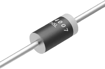
diode-1n40071N4007 Diode
General-purpose rectifier
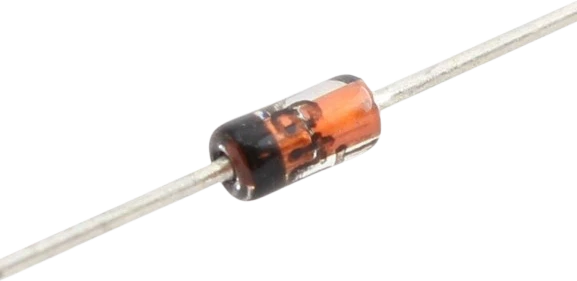
diode-1n41481N4148 Diode
Fast switching diode
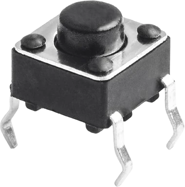
push-buttonPush Button
Momentary digital input
Build with the 100nF Ceramic Capacitor.
Drop the 100nF Ceramic Capacitor into a circuit, write firmware, and simulate it in your browser, then deploy to real hardware. All in one editable Tinkered project.