10kΩ Resistor
A 10 kΩ fixed axial resistor (0.25W carbon film) used for pull-ups, pull-downs, voltage dividers, and biasing.

What is the 10kΩ Resistor?
The 10kΩ resistor is a two-terminal, non-polarized passive component with a fixed resistance of 10,000 ohms. It obeys Ohm's law (I = V/R), so the current through it is simply the voltage across it divided by 10kΩ. 10kΩ is a standard E24 value, and in a typical 0.25W carbon film part the body measures about 6.3mm long and 2.5mm in diameter with two axial leads.
10kΩ is one of the most-used values in hobby electronics. It is the default choice for pull-up and pull-down resistors, a common element in voltage dividers, and a frequent base-bias resistor for small-signal transistors. The value is high enough to draw very little current (about 0.5mA at 5V) yet low enough to hold a logic line firmly at a defined level.
A standard 1/4W part is rated for 0.25W of dissipation, which at 10kΩ corresponds to roughly 50V across it before reaching the power limit. In 3.3-5V logic circuits it dissipates well under a milliwatt, so heating is rarely a concern. Carbon film versions carry a ±5% tolerance (gold band), with a color code of brown, black, orange, gold.
Specifications
- Dimensions
- 6.3 × 2.5 × 2.5 mm
Verified from the Tinkered component library.
Circuit requirements
- Non-polarized: either lead can connect either way, so there is no orientation to observe.
- As a pull-up or pull-down, connect one end to VCC or GND and the other to the input pin; 10kΩ is the conventional default for pushbuttons and open-drain lines.
- In a voltage divider the output is Vin x R2 / (R1 + R2); two 10kΩ resistors in series give a clean half-supply reference.
- As a BJT base resistor, 10kΩ sets the base current (about 0.43mA from a 5V pin), enough to saturate small-signal transistors like the 2N2222 for light loads.
- Do not use 10kΩ to current-limit an LED: at 5V it passes only about 0.3mA, far below the few mA an LED needs to light visibly, so use roughly 220-330Ω instead.
- Keep dissipation within the 0.25W rating (P = V^2 / R), which means keeping the voltage across a 10kΩ part below about 50V.
- For I2C pull-ups, 10kΩ is fine at 100kHz standard mode but can be too weak at 400kHz on long or heavily loaded buses; drop to 4.7kΩ or 2.2kΩ if the rising edges are slow.
Common 10kΩ Resistor mistakes
Using 10kΩ as an LED series resistor
A 10kΩ resistor limits LED current to roughly 0.3mA at 5V, so the LED appears very dim or dark. Beginners often grab 10kΩ by mistake; the correct current-limiting value for a standard LED is around 220-330Ω.
Misreading the color bands
10kΩ ±5% reads brown, black, orange, gold. Swapping the orange (x1000) multiplier band for red gives 1kΩ and for yellow gives 100kΩ, so a single misread band changes the value by an order of magnitude.
Measuring resistance in-circuit
Probing a 10kΩ resistor while it is still soldered into a board reads it in parallel with the rest of the circuit, giving a value lower than 10kΩ. Remove at least one lead, or measure with power off and the part isolated, for an accurate reading.
Treating ±5% as an exact value
A ±5% 10kΩ resistor can measure anywhere from 9.5kΩ to 10.5kΩ. For precision voltage dividers or reference circuits, use ±1% metal film parts rather than assuming the printed value is exact.
Picking too weak a pull-up
10kΩ is a safe general-purpose pull-up, but on fast or capacitively loaded lines (high-speed I2C, long wiring) it can slow the rising edge and cause errors. Lower the value to 4.7kΩ or 2.2kΩ when signal edges look sluggish.
More passives & discretes

resistor-220220Ω Resistor
Custom resistance values supported

resistor-1k1kΩ Resistor
Custom resistance values supported
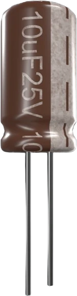
capacitor-ceramic100nF Ceramic Capacitor
Custom capacitance values supported
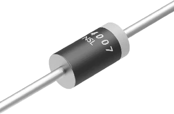
diode-1n40071N4007 Diode
General-purpose rectifier
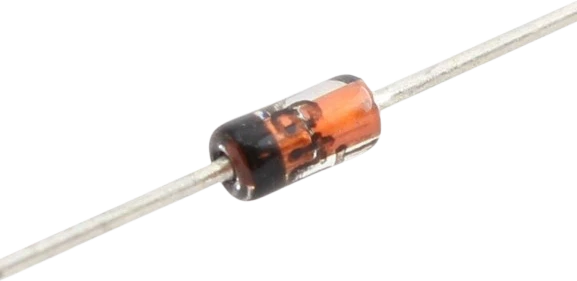
diode-1n41481N4148 Diode
Fast switching diode
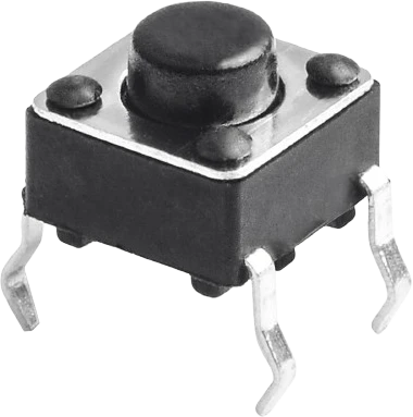
push-buttonPush Button
Momentary digital input
Build with the 10kΩ Resistor.
Drop the 10kΩ Resistor into a circuit, write firmware, and simulate it in your browser, then deploy to real hardware. All in one editable Tinkered project.