Knob-controlled LED dimmer
Read the wiper on A0 and map it to a PWM pin to fade an LED up and down by hand. This is the classic first analog-input sketch.
A 10kΩ three-terminal rotary potentiometer that acts as an adjustable voltage divider or variable resistor, with custom resistance values supported.
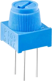
A potentiometer is a three-terminal variable resistor. The two outer legs (VCC and GND here) span the full track resistance, and a wiper (the SIG pin) slides along that track to tap off any point between them. Because the wiper splits the total resistance into two parts that always sum to the whole, the part behaves as an adjustable voltage divider when all three legs are used.
With a linear taper, the wiper voltage rises in proportion to shaft position: at the far ends you get roughly VCC or GND, and at center you get about half of VCC. Feeding the wiper into a microcontroller analog input lets the code read knob position directly. On an Arduino Uno the 10-bit ADC returns 0 to 1023 across the 0 to 5V range. The body is compact at 9.5mm wide, 11mm tall, and 5mm deep.
The default value is 10kΩ, though custom resistance values are supported for this part. Ordinary carbon potentiometers of this size are low-power devices (commonly a fraction of a watt) with a wide tolerance (often around plus or minus 20 percent), so they are meant for control and sensing rather than for carrying significant current.
| Pin | Function | Type |
|---|---|---|
VCC VCC | Power | Power in |
SIG Signal (Wiper) | Analog | Passive |
GND GND | Power | Power in |
Verified from the Tinkered component library.
Connecting only two legs leaves the analog pin floating, so readings drift with noise. For a clean analogRead, use the full three-leg divider with VCC and GND on the outer legs.
A digital pin only sees HIGH or LOW, so the knob appears to jump between two states. Route the wiper to an analog input (A0 to A5 on an Uno) to read the continuous position.
Logarithmic (audio) taper pots do not map position to voltage evenly, so the reading crowds toward one end. Confirm the part is linear taper when you want a smooth, proportional analog scale.
Wide tolerance means the end-to-end resistance and the center point will not be exactly 10kΩ or exactly half. Calibrate the min and max in software if you need accuracy.
If turning the knob raises the value when you expected it to fall, the VCC and GND legs are swapped. Reverse the outer connections or flip the reading in code.
Read the wiper on A0 and map it to a PWM pin to fade an LED up and down by hand. This is the classic first analog-input sketch.
Map the pot's 0 to 1023 reading onto 0 to 180 degrees to steer a hobby servo directly from the knob, a common intro to reading sensors and driving actuators together.

resistor-220Custom resistance values supported

resistor-1kCustom resistance values supported

resistor-10kCustom resistance values supported
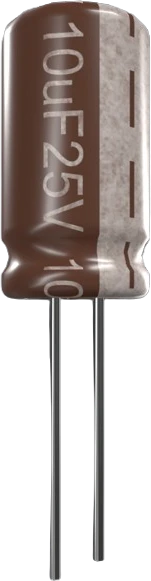
capacitor-ceramicCustom capacitance values supported
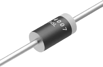
diode-1n4007General-purpose rectifier
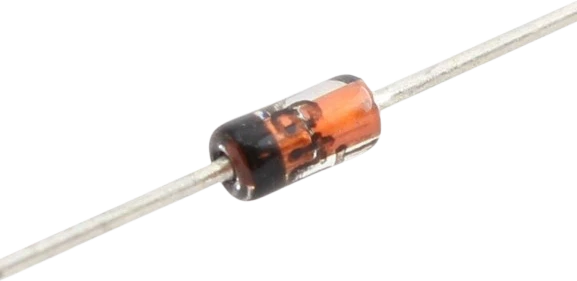
diode-1n4148Fast switching diode
Drop the 10kΩ Potentiometer into a circuit, write firmware, and simulate it in your browser, then deploy to real hardware. All in one editable Tinkered project.