10kΩ Rotary Potentiometer
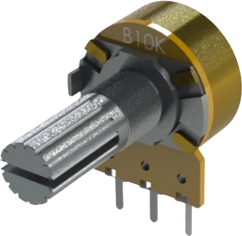
A 10kΩ linear-taper rotary potentiometer: a 3-terminal variable resistor that works as an adjustable voltage divider for analog control.
What is the 10kΩ Rotary Potentiometer?
The 10kΩ rotary potentiometer is a single-turn, panel-mount variable resistor built around a resistive track and a movable wiper. Turning the shaft sweeps the wiper across the track, so the resistance between the wiper and each end terminal changes smoothly. The two outer terminals sit at the ends of the 10kΩ track and the center terminal is the wiper. In this simulator the terminals are labeled VCC, Signal (Wiper), and GND to reflect a typical divider hookup, but electrically the two outer pins are interchangeable ends of the same track.
It uses a linear (Type B) taper, meaning resistance and the resulting output voltage change in direct proportion to shaft angle. That linear response is what makes it the standard choice for microcontroller analog input, since a given number of degrees of rotation always maps to the same change in the ADC reading. The shaft covers roughly 300 degrees of mechanical travel between its end stops.
Wired as a voltage divider with the ends across a supply, the wiper outputs a voltage that swings between the two rail voltages as you turn the knob. Fed into an analog-to-digital pin, this gives a low-cost, tactile way to set brightness, volume, speed, thresholds, or menu selections. The 10kΩ value is a good middle ground: high enough to draw negligible current from a 5V or 3.3V rail, low enough to present a source impedance most microcontroller ADCs can sample cleanly.
10kΩ Rotary Potentiometer pinout
| Pin | Function | Type |
|---|---|---|
VCC VCC | Power | Power in |
SIG Signal (Wiper) | Analog | Passive |
GND GND | Power | Power in |
Specifications
- Dimensions
- 16 × 25 × 16 mm
Verified from the Tinkered component library.
Circuit requirements
- Divider wiring: connect one outer terminal to VCC and the other to GND, and take the analog output from the center wiper pin. The wiper voltage then ranges from GND to VCC as the shaft turns.
- Match the supply to your ADC reference. Powering the outer terminals from the same rail as the microcontroller (5V on an Uno, 3.3V on 3.3V boards) keeps the full rotation mapped across the ADC's input range.
- Swapping the two outer terminals simply reverses the direction of travel (clockwise decreases instead of increases). This is a wiring choice, not a fault.
- The wiper is a relatively high-impedance node. Keep the wire to the ADC pin short, and if readings are noisy add a small capacitor (for example 0.1µF) from the wiper to GND to filter it.
- Do not float the wiper. If the center pin is left unconnected the ADC input will read drifting noise; always route it to a defined load or input.
- Using it as a two-terminal rheostat (wiper plus one end) to limit current directly is risky: near the low-resistance end it approaches a short, and the track's small power rating can be exceeded. Always keep a fixed series resistor in the path when driving a load like an LED.
Common 10kΩ Rotary Potentiometer mistakes
Confusing the wiper with an end terminal
The center pin is always the wiper (the analog output). Wiring the ADC to an outer pin instead gives a fixed reading that never changes with rotation. Take your signal from the middle terminal and put the supply across the two outer ones.
Using a log/audio taper where linear is needed
A 10k that looks identical may be an audio (Type A) taper. Its output is nonlinear, so equal knob movements produce unequal ADC changes and the midpoint sits far from 50%. For predictable microcontroller mapping use the linear (Type B) part.
Driving a load through the wiper without a series resistor
Turning the pot toward minimum resistance can approach a near-short and push current past the track's low power rating, overheating or damaging it. Keep a current-limiting resistor in series and never rely on the pot alone to set LED or motor current.
Expecting a perfect 0 V to full-scale swing
End resistance, contact resistance, and ADC noise mean the extremes may not read exactly 0 or the maximum count. Calibrate in software or add a small deadband rather than assuming the raw endpoints are exact.
Leaving the wiper unconnected while reading it
A floating center pin lets the high-impedance ADC input pick up stray noise, producing jumpy values. Always connect the wiper to the input you intend to read and keep the divider ends tied to the rails.
More passives & discretes

resistor-220220Ω Resistor
Custom resistance values supported

resistor-1k1kΩ Resistor
Custom resistance values supported

resistor-10k10kΩ Resistor
Custom resistance values supported
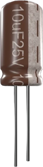
capacitor-ceramic100nF Ceramic Capacitor
Custom capacitance values supported
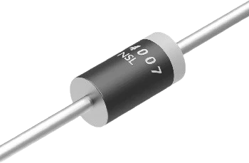
diode-1n40071N4007 Diode
General-purpose rectifier
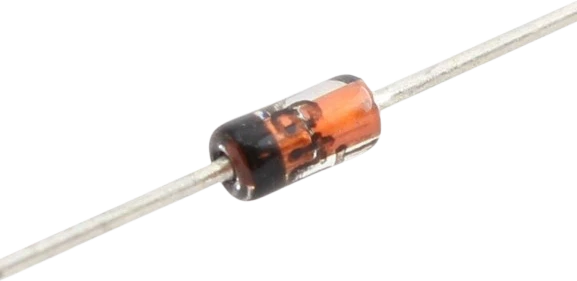
diode-1n41481N4148 Diode
Fast switching diode
Build with the 10kΩ Rotary Potentiometer.
Drop the 10kΩ Rotary Potentiometer into a circuit, write firmware, and simulate it in your browser, then deploy to real hardware. All in one editable Tinkered project.