RFID door lock
Tap-to-enter access control that releases a solenoid or drives a servo when an authorized card or key fob is scanned.
A 13.56 MHz contactless RFID reader/writer module built on NXP's MFRC522 IC, reading and writing ISO/IEC 14443A MIFARE cards over a 3.3V SPI bus.
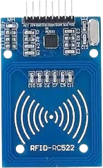
The RC522 mounts NXP's MFRC522 contactless reader IC on a small breakout with an etched PCB antenna. It operates at 13.56 MHz and both reads and writes ISO/IEC 14443A transponders, including MIFARE Classic 1K and 4K, MIFARE Ultralight, and NTAG cards and key fobs. A microcontroller drives it over SPI at clock rates up to 10 Mbit/s.
In reader mode the module generates the 13.56 MHz RF field through its onboard antenna, powers the passive card inductively, and exchanges data at rates up to 848 kbit/s. Typical read and write range is up to about 50 mm and varies with antenna tuning and card type. For MIFARE Classic cards, the MFRC522 handles the CRYPTO1 authentication needed to unlock protected sectors before reading or writing block data.
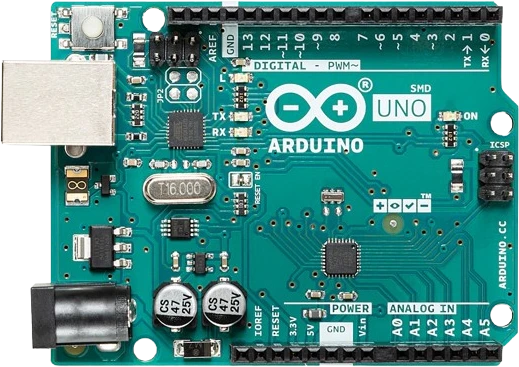
The MFRC522 chip itself also supports I2C and UART, but this module breaks out only the SPI pins plus a reset (RST) line and an interrupt (IRQ) line. It runs from a 3.3V supply and expects 3.3V logic, so pair it with a 3.3V board directly or add level shifting when connecting to a 5V microcontroller.
| Pin | Function | Type |
|---|---|---|
SDA SDA / SS | SPI CS | Digital input |
SCK SCK | SPI SCK | Digital input |
MOSI MOSI | SPI MOSI | Digital input |
MISO MISO | SPI MISO | Digital output |
IRQ IRQ | Digital interrupt | Digital output |
GND GND | Power | Power in |
RST RST | Digital reset | Digital input |
3V3 3.3V | Power | Power in |
Verified from the Tinkered component library · SunFounder.
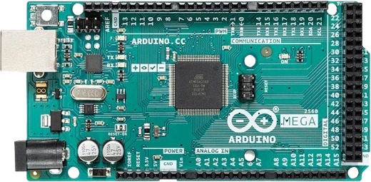
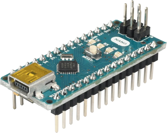
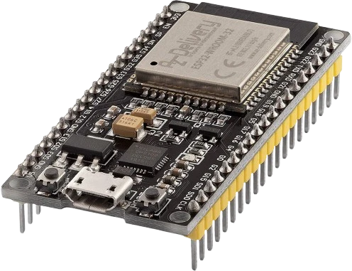
The MFRC522 RFID Reader connects to any of the microcontrollers supported in Tinkered. Mind the 3.3 V logic level on 3.3 V boards.
The MFRC522 RFID Reader is fully simulated in Tinkered. Wire it into a circuit, write your firmware, and read real values back with no physical hardware. Test your logic before you touch a breadboard.
Open it in the simulatorThe board and the MFRC522 IC run on 3.3V, with a 3.6V absolute maximum. Connecting the supply pin to a 5V rail can permanently damage the module.
SCK, MOSI, SDA/SS, and RST are 3.3V inputs. Wiring them straight to a 5V Arduino pushes the pins past their rated voltage. Add a level shifter on those lines for dependable, in-spec operation.
The pin labeled SDA is the SPI slave-select line, not I2C data. It must connect to the SS pin declared in your sketch, and the SS number in code has to match the wiring.
Most RC522 libraries require a reset pin in the constructor. Skipping it, or leaving RST floating, prevents the chip from initializing and no cards are detected.
Metal surfaces and closely stacked cards detune the 13.56 MHz antenna and can cut range to near zero. Keep the PCB antenna clear of metal and present one card at a time.
Tap-to-enter access control that releases a solenoid or drives a servo when an authorized card or key fob is scanned.
Record each person's card UID with a timestamp to an SD card or the serial monitor for classroom or workshop sign-in.
Deduct a stored balance from a MIFARE card to dispense an item, demonstrating the basics of contactless payment.
Scan tagged tools or parts in and out to keep a running record of what has left the shelf.
Read card UIDs to trigger LEDs, sounds, or LCD messages, a common first project for understanding NFC-style tags.
Drop the MFRC522 RFID Reader into a circuit, write firmware, and simulate it in your browser, then deploy to real hardware. All in one editable Tinkered project.