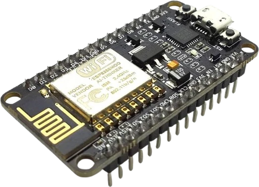
Temperature and humidity monitor
Pair the 1602 with a DHT22 or similar sensor and print live readings across the two lines, a classic first display project.
A 16x2 character LCD module built on the HD44780-compatible controller, driven over a 4-bit or 8-bit parallel interface at 5V.
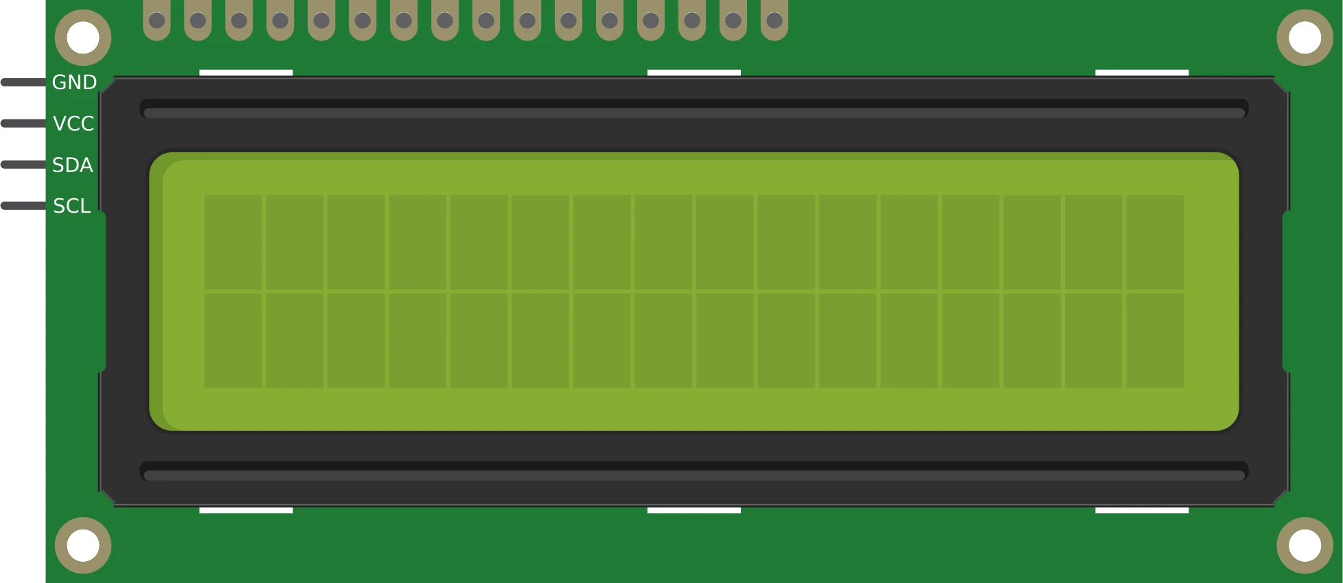
The LCD 1602 Parallel is a 16-character by 2-line alphanumeric display based on the industry-standard HD44780 controller/driver (the ADM1602K-NSW-FBS variant). Each of the 32 cells renders characters on a 5x8 dot matrix using a 1/16 duty STN liquid-crystal panel, and the on-board controller holds a built-in character ROM so a microcontroller only has to send ASCII bytes and a handful of commands.
Communication happens over a parallel bus rather than a serial one. The module exposes eight data lines (D0-D7) plus three control lines: RS (Register Select) to choose between command and data, RW (Read/Write) to pick direction, and E (Enable) to latch each transfer. It can run in full 8-bit mode using all eight data lines, or in 4-bit mode that uses only D4-D7 and sends each byte as two nibbles, cutting the required GPIO count roughly in half.
The panel itself is not self-lit. Contrast is set by an analog voltage on the V0 pin, and a separate LED backlight is powered through the BLA (anode) and BLK (cathode) pins. The module measures about 80 x 36 x 12 mm and runs from a single 5V supply, which is why libraries like Arduino's LiquidCrystal target it directly.
| Pin | Function | Type |
|---|---|---|
VSS GND | Power | Power in |
VDD VCC (5V) | Power | Power in |
V0 Contrast | Passive | Passive |
RS RS (Register Select) | Digital input | Digital input |
RW RW (Read/Write) | Digital input | Digital input |
E E (Enable) | Digital input | Digital input |
D0 D0 | Free | Free |
D1 D1 | Free | Free |
D2 D2 | Free | Free |
D3 D3 | Free | Free |
D4 D4 | Bidirectional (GPIO) | Bidirectional (GPIO) |
D5 D5 | Bidirectional (GPIO) | Bidirectional (GPIO) |
D6 D6 | Bidirectional (GPIO) | Bidirectional (GPIO) |
D7 D7 | Bidirectional (GPIO) | Bidirectional (GPIO) |
BLA Backlight + | Passive | Passive |
BLK Backlight - | Passive | Passive |
Verified from the Tinkered component library.
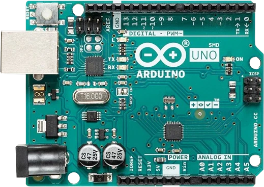
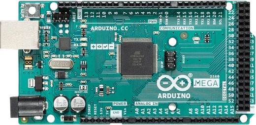
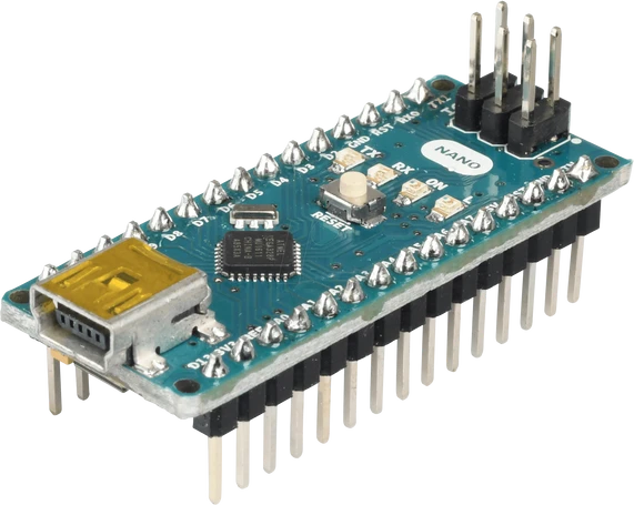
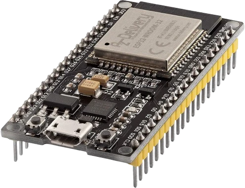
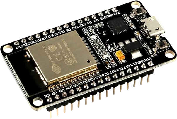
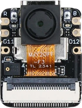
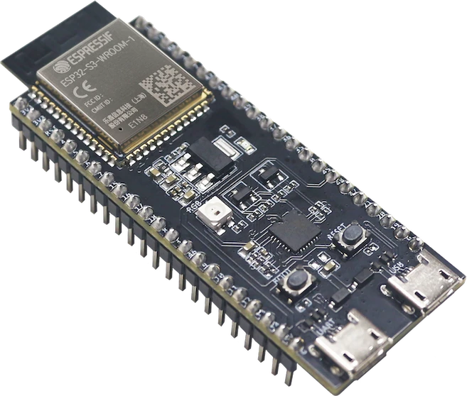
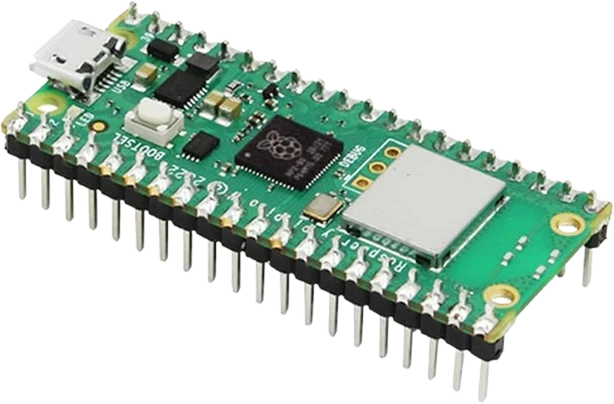
The LCD 1602 Parallel connects to any of the microcontrollers supported in Tinkered. Mind the 5 V logic level on 3.3 V boards.
The LCD 1602 Parallel is fully simulated in Tinkered. Wire it into a circuit, write your firmware, and read real values back with no physical hardware. Test your logic before you touch a breadboard.
Open it in the simulatorWiring power and data but leaving V0 unconnected is the most common cause of a display that looks dead or shows only full blocks. V0 needs an adjustable voltage from a 10k pot before any characters become visible.
If you never read from the display, RW should be tied to GND. Leaving it floating can leave the controller in an undefined read/write state and produce garbled or no output.
Wiring all eight data lines but initializing the library in 4-bit mode (or the reverse) sends data on pins the controller is not reading. Decide on 4-bit (D4-D7 only) or 8-bit (D0-D7) and keep the wiring and code consistent.
BLA and BLK feed an LED backlight. Connecting BLA straight to 5V without a series resistor (when the module lacks an on-board one) can over-drive and shorten the life of the backlight.
The bare parallel 1602 needs at least six GPIO lines plus contrast wiring. Tutorials written for the I2C backpack version assume a two-wire SDA/SCL hookup and will not match this pinout.
Pair the 1602 with a DHT22 or similar sensor and print live readings across the two lines, a classic first display project.
Combine an RTC module with the 1602 to show time and date, or build a countdown timer with button inputs.
Use the two rows plus a rotary encoder or buttons to build a scrolling menu for setting parameters on a larger project.
Show potentiometer, distance, or light-sensor values in real time, using custom characters for simple bar graphs on the 5x8 cells.
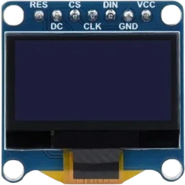
oled-128x64Monochrome I²C display
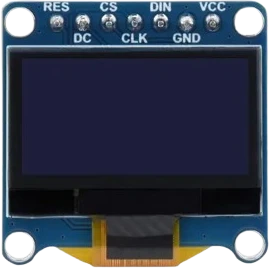
oled-sh1107-128x128Square monochrome OLED
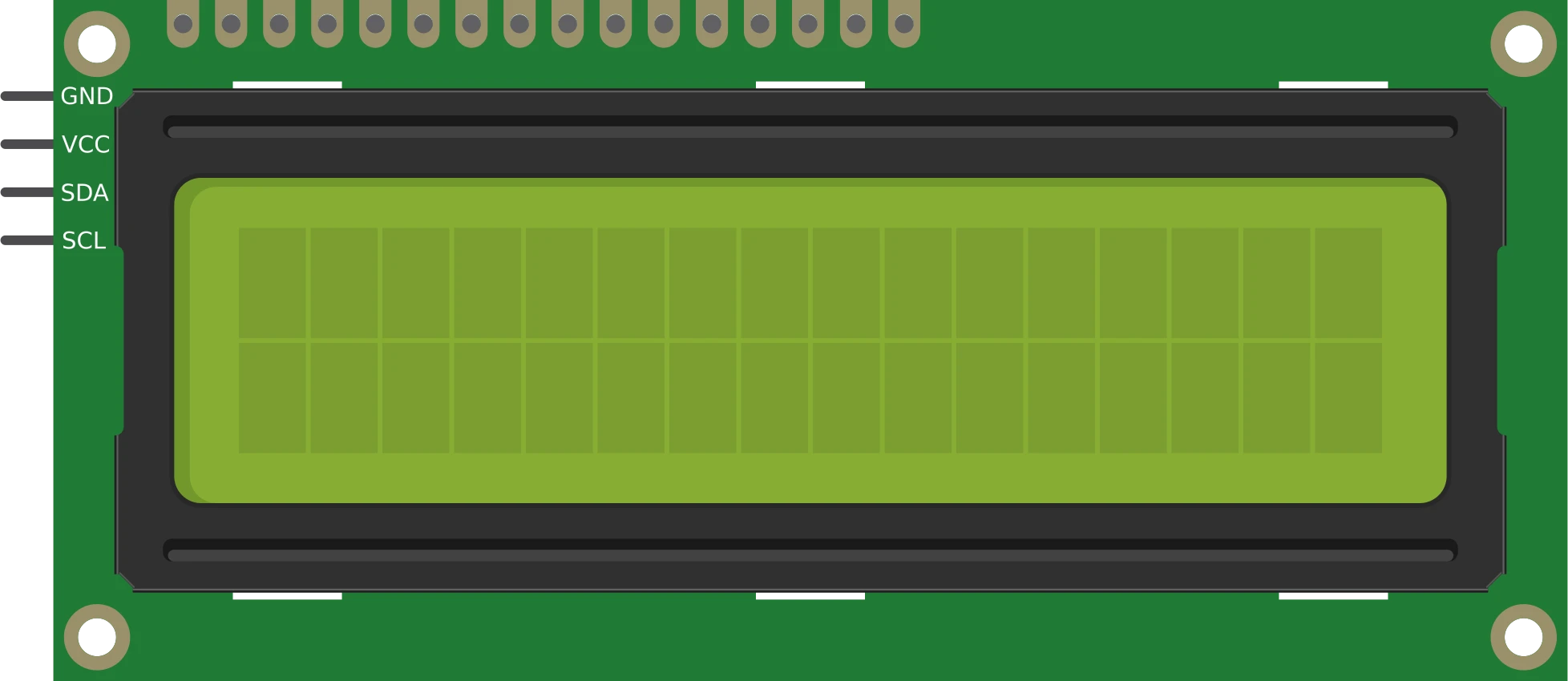
lcd-1602-i2c16×2 character display
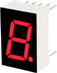
7seg-displaySingle numeric digit
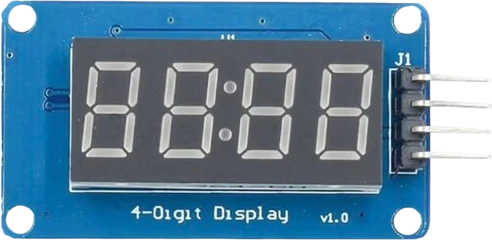
tm1637-4digit-displayFour-digit segment module
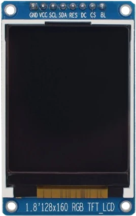
st7735-tft-1-8Color SPI display
Drop the LCD 1602 Parallel into a circuit, write firmware, and simulate it in your browser, then deploy to real hardware. All in one editable Tinkered project.