Sensor dashboard
Show live temperature, humidity, or other sensor readings as large text and simple gauges on a compact color screen.
A 1.8-inch 128x160 color TFT LCD breakout driven by an ST7735S controller over a 4-wire SPI interface.
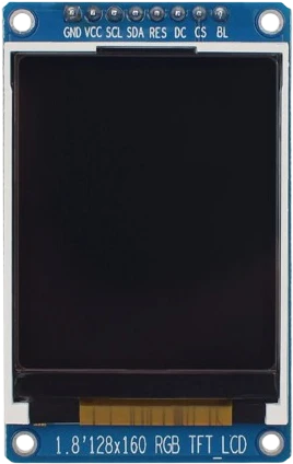
The ST7735 1.8-inch TFT is a small color graphic display built around the ST7735S controller. This particular breakout is the LCDWiki MSP1803 (and pin-compatible generics), with a 128x160 pixel panel that renders roughly 65K (16-bit) colors. The active viewing area measures about 28.03 x 35.04 mm on a 34.5 x 58.0 mm PCB, making it a compact way to add graphics, text, and simple UI to a microcontroller project.
It talks to the host over a 4-wire SPI bus using CS (chip select), SCK (clock), SDA/MOSI (data), plus an A0 data/command line and a RESET line. There is no data-out pin, so the TFT is write-only over SPI. The module is well supported by common libraries such as Adafruit's ST7735 driver and TFT_eSPI, which handle the ST7735 initialization and drawing primitives.
The board accepts 3.3-5V on VCC, but its logic operates at 3.3V TTL, and a separate LED pin controls the backlight. Many MSP1803 boards also include an onboard microSD/TF card slot on separate SPI pins, which is handy for loading bitmaps and fonts, though the display and card are driven independently.
| Pin | Function | Type |
|---|---|---|
VCC VCC (3.3-5V) | Power | Power in |
GND GND | Power | Power in |
CS CS | SPI CS | Digital input |
RESET RESET | Digital active-low reset | Digital input |
A0 A0 | SPI data/command select | Digital input |
SDA SDA / MOSI | SPI MOSI | Digital input |
SCK SCK | SPI SCK | Digital input |
LED LED (backlight) | Digital backlight enable, tie high if not dimmed | Digital input |
Verified from the Tinkered component library · LCDWiki / generic ST7735S breakout (MSP1803).
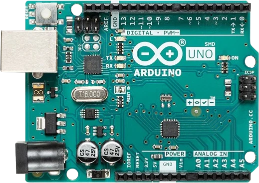
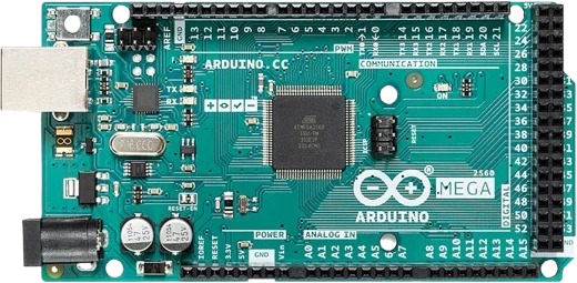
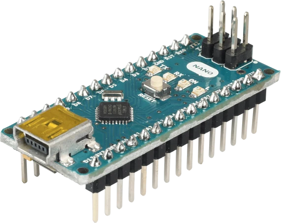
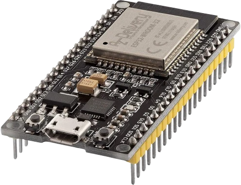
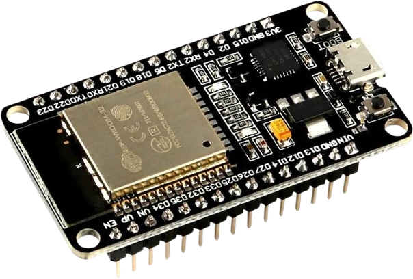
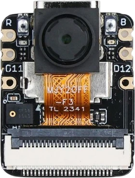
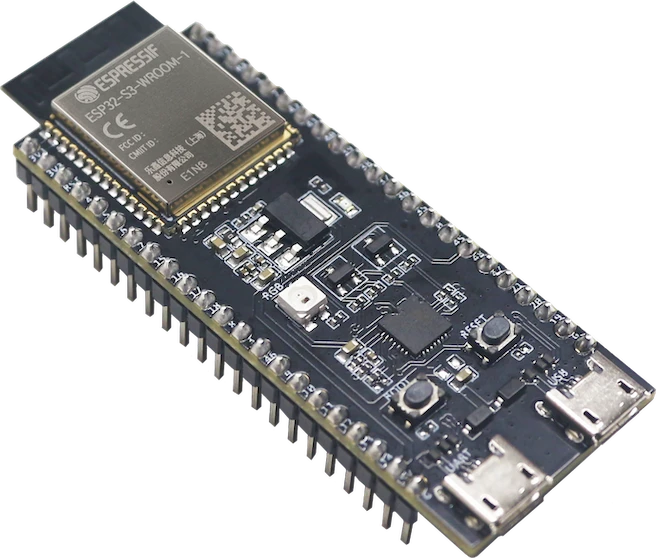
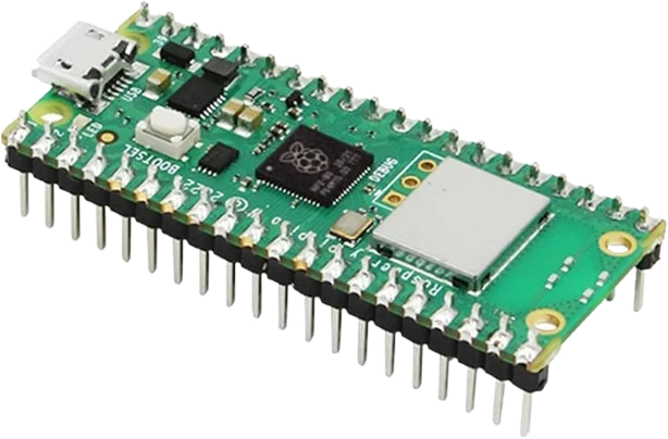
The ST7735 TFT 1.8-inch connects to any of the microcontrollers supported in Tinkered. Mind the 3.3 V logic level on 3.3 V boards.
The ST7735 TFT 1.8-inch is fully simulated in Tinkered. Wire it into a circuit, write your firmware, and read real values back with no physical hardware. Test your logic before you touch a breadboard.
Open it in the simulatorVCC tolerates 3.3-5V, which fools people into assuming the whole module is 5V-safe. The ST7735S logic is 3.3V TTL. Connecting SCK, SDA, A0, CS, and RESET straight to 5V outputs overstresses the controller inputs. Use a level shifter or a 3.3V host for the signal lines.
ST7735 panels ship in several variants (often called red, green, or black tab, or INITR options in libraries). Picking the wrong one produces a shifted image with a colored border, inverted colors, or swapped red/blue channels. Try the alternate init constant if the image looks offset or the colors are wrong.
If SPI is wired correctly but the screen stays black, the backlight is usually the cause. The LED pin must be tied high (or PWM-driven) for the panel to be visible; the controller can be initialized and drawing while the display still looks dark.
A0 is not optional and cannot be strapped to a fixed level. The library toggles it to distinguish commands from pixel data. Miswiring it to the wrong pin (or to VCC/GND) results in a blank or garbled screen even though power and clock look fine.
A floating RESET can leave the ST7735S in an undefined state so it never initializes. Connect RESET to a GPIO so the library can pulse it, or at minimum tie it high through the board's reset circuit.
Show live temperature, humidity, or other sensor readings as large text and simple gauges on a compact color screen.
Drive a color clock face, weather icon, or system status readout for a desk gadget or home automation node.
The 128x160 pixel canvas and fast SPI make it a good target for tile-based graphics, sprites, and simple arcade-style games.
Load and display bitmap images from the onboard microSD/TF card slot for a photo frame or asset-driven UI.
Plot ADC readings or signal traces over time for a lightweight oscilloscope-style or logging display.
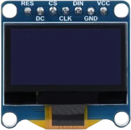
oled-128x64Monochrome I²C display
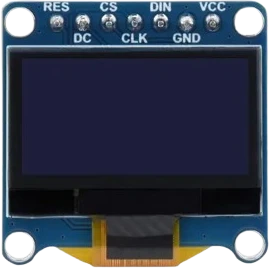
oled-sh1107-128x128Square monochrome OLED
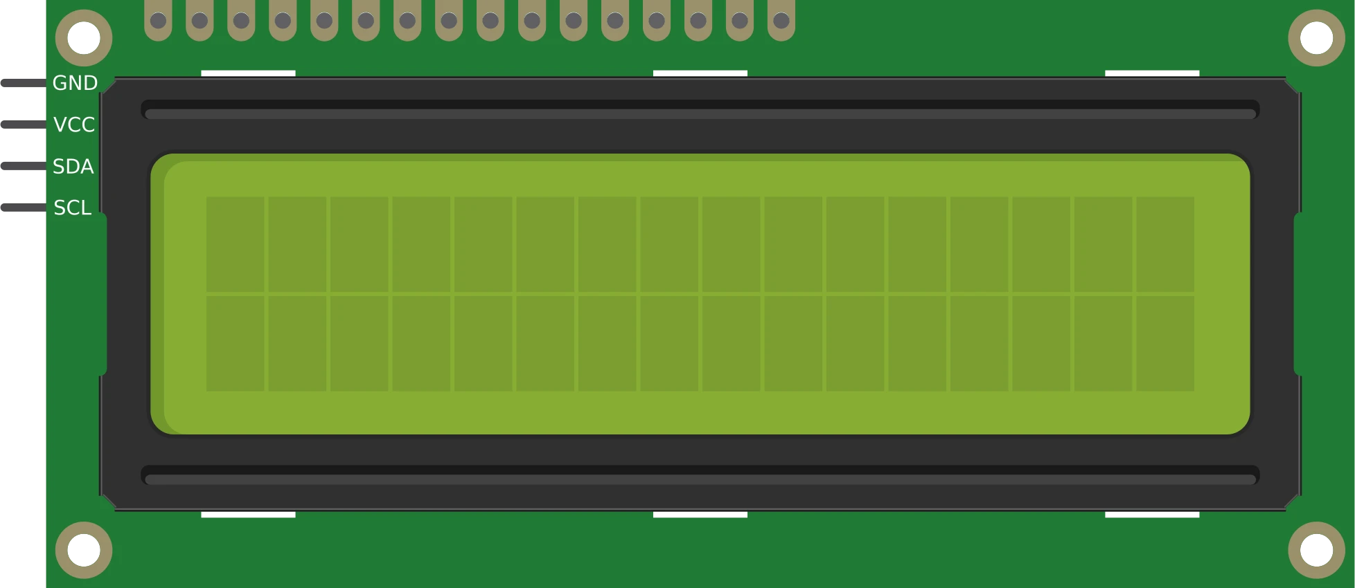
lcd-1602-i2c16×2 character display
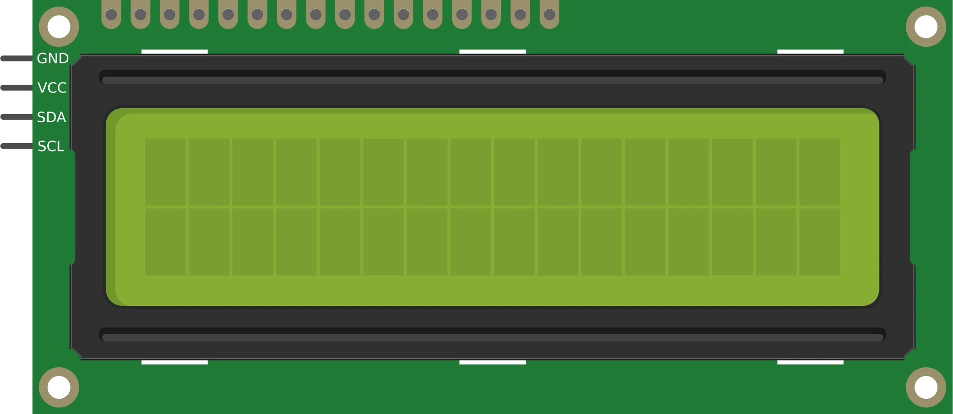
lcd-1602-parallel16×2 character display
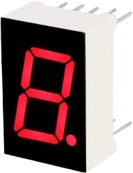
7seg-displaySingle numeric digit
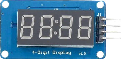
tm1637-4digit-displayFour-digit segment module
Drop the ST7735 TFT 1.8-inch into a circuit, write firmware, and simulate it in your browser, then deploy to real hardware. All in one editable Tinkered project.