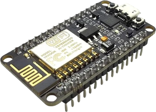
Scrolling text marquee
Chain four 8x8 modules into a 32x8 strip and scroll messages, clocks, or sensor readouts across it using a MAX7219 text library.
A serial-input common-cathode LED driver IC paired with an 8x8 dot-matrix, controlling all 64 LEDs over three signal wires.
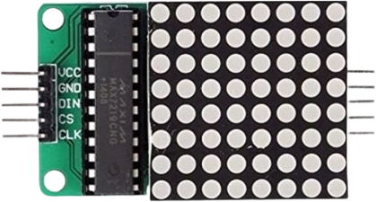
The MAX7219 LED matrix module combines the Maxim/Analog Devices MAX7219 display driver IC with an 8x8 dot-matrix of 64 LEDs on a small carrier PCB. The driver handles multiplex scanning, per-segment control, brightness, and (for 7-segment use) BCD decoding entirely on-chip, so the microcontroller only shifts display data in over a simple serial link. A single external resistor sets the peak segment current for every LED.
Control uses a 4-wire serial interface: DIN, CLK, and LOAD/CS for data, plus V+ and GND. The shift register clocks at up to 10MHz. A DOUT pin lets modules daisy-chain, so one to four (or more) 8x8 modules can be strung together and driven from the same three signal lines, which is why these are sold as single, dual, and quad matrix strips.
On-chip control registers provide digital brightness in 16 steps, a scan-limit register to display 1 to 8 digits (or rows), an optional code-B decode mode for 7-segment digits, a display-test mode that forces all LEDs on, and a 150uA low-power shutdown that retains the display data. The part drives common-cathode displays and is specified for a 4.0 to 5.5V supply.
Every specification is cited to its source.
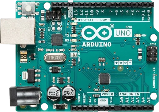
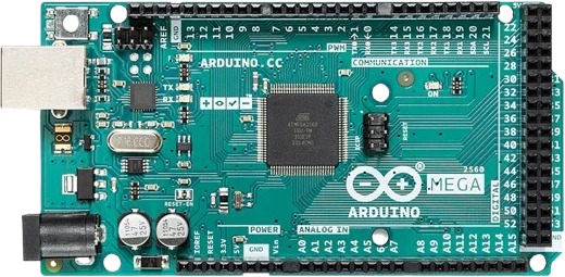
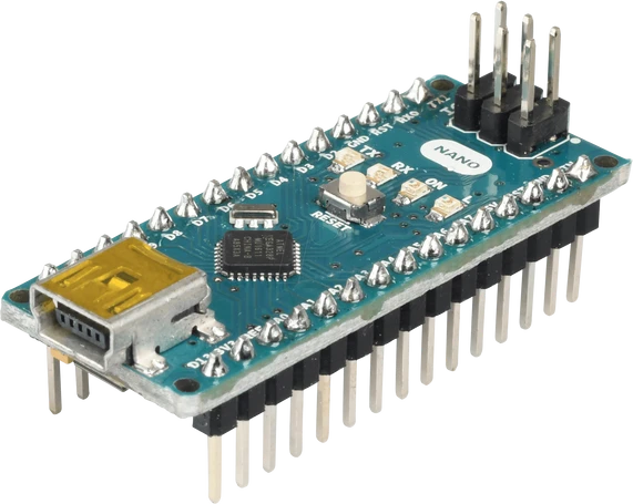
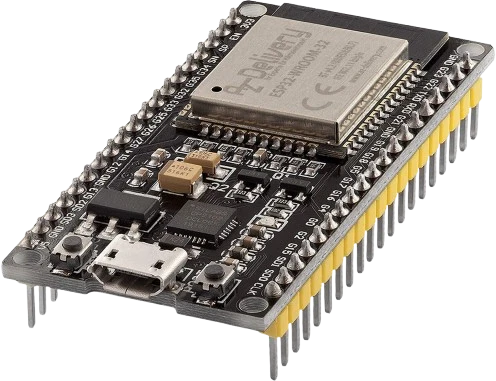
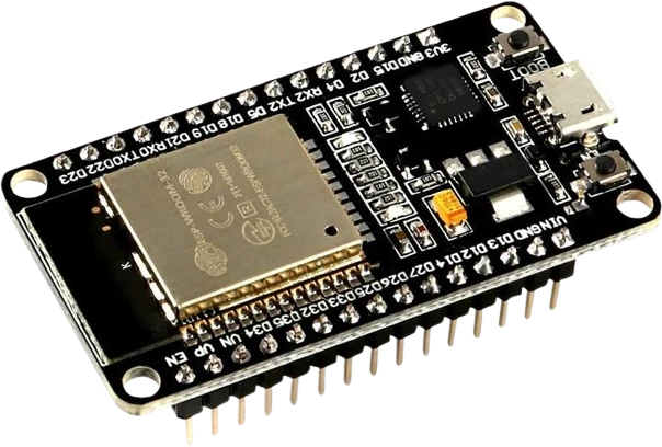
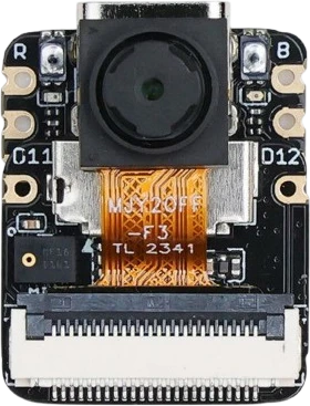
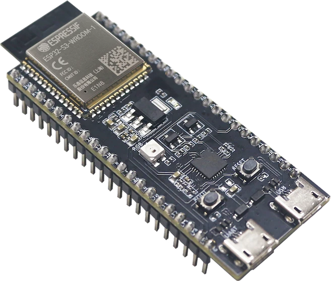
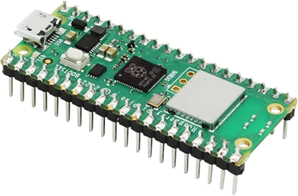
The MAX7219 LED Matrix connects to any of the microcontrollers supported in Tinkered.
On a matrix you must write 0x00 to the decode-mode register (0x09). If the code-B BCD decoder is left on, the driver interprets your pixel data as 7-segment font digits and the display shows garbage instead of the dots you set.
The display is blanked on power-up. If you never write the shutdown register to normal operation and set the scan-limit register to all 8 digits, the panel stays dark or lights only a few rows even though your data is loading.
Each fully lit 8x8 module can draw a lot of current at 40mA per segment. Chaining four modules off the 5V pin of a USB-powered Arduino can brown out the board; use a dedicated 5V supply and common ground.
With the ISET pin left open (no RSET) there is no segment current and the display stays dark. Fitting a resistor below the 9.53k ohm minimum drives segments past their 40mA rating, risking LED and driver damage. Keep the on-board resistor or adjust brightness digitally via the intensity register instead.
Generic MAX7219 modules differ in physical LED orientation and row/column mapping. Selecting the wrong hardware type in a library (for example FC16 vs GENERIC vs ICSTATION in MD_MAX72XX) makes text appear upside down, mirrored, or split across the wrong modules even though wiring is correct.
Chain four 8x8 modules into a 32x8 strip and scroll messages, clocks, or sensor readouts across it using a MAX7219 text library.
Pair the matrix with an RTC module to show the time in a compact scrolling or static font, a classic desk-clock build.
Snake, Pong, and falling-block games map neatly onto the 64-pixel grid, using the driver's fast full-frame updates for smooth animation.
Drive the columns from an analog audio envelope or FFT bins to turn the matrix into a bar-graph level meter that reacts to sound.
Show icons, weather glyphs, or notification counts from a connected ESP32/ESP8266, updating the matrix over Wi-Fi.
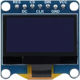
oled-128x64Monochrome I²C display
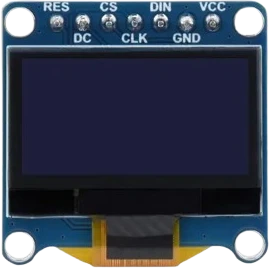
oled-sh1107-128x128Square monochrome OLED
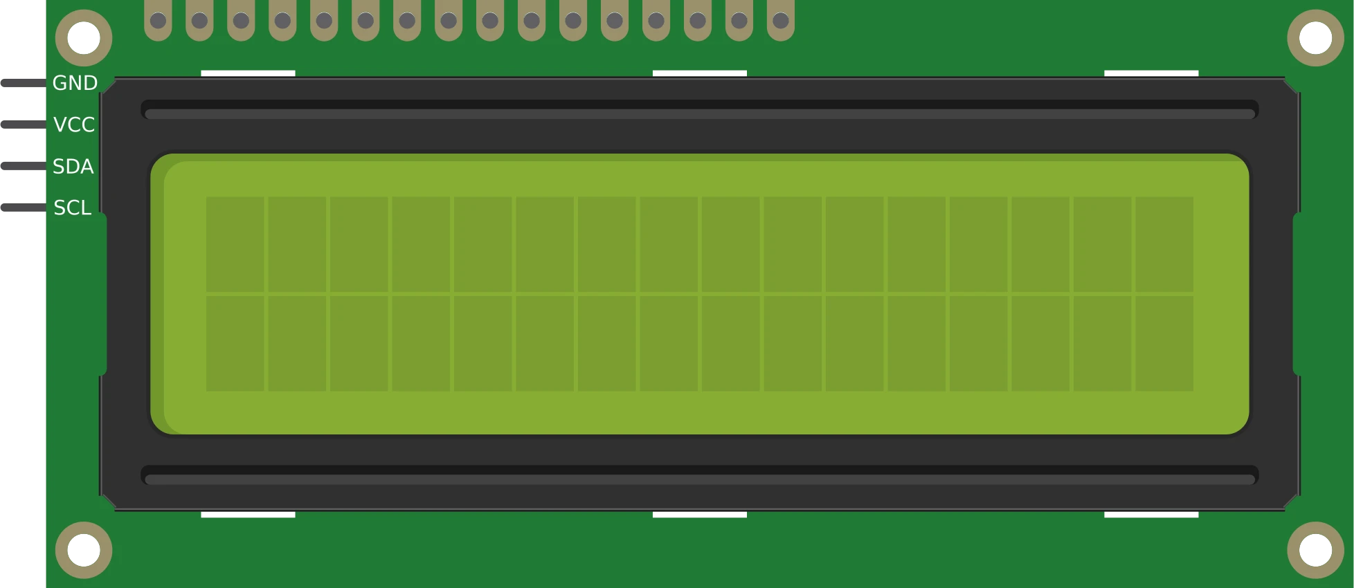
lcd-1602-i2c16×2 character display
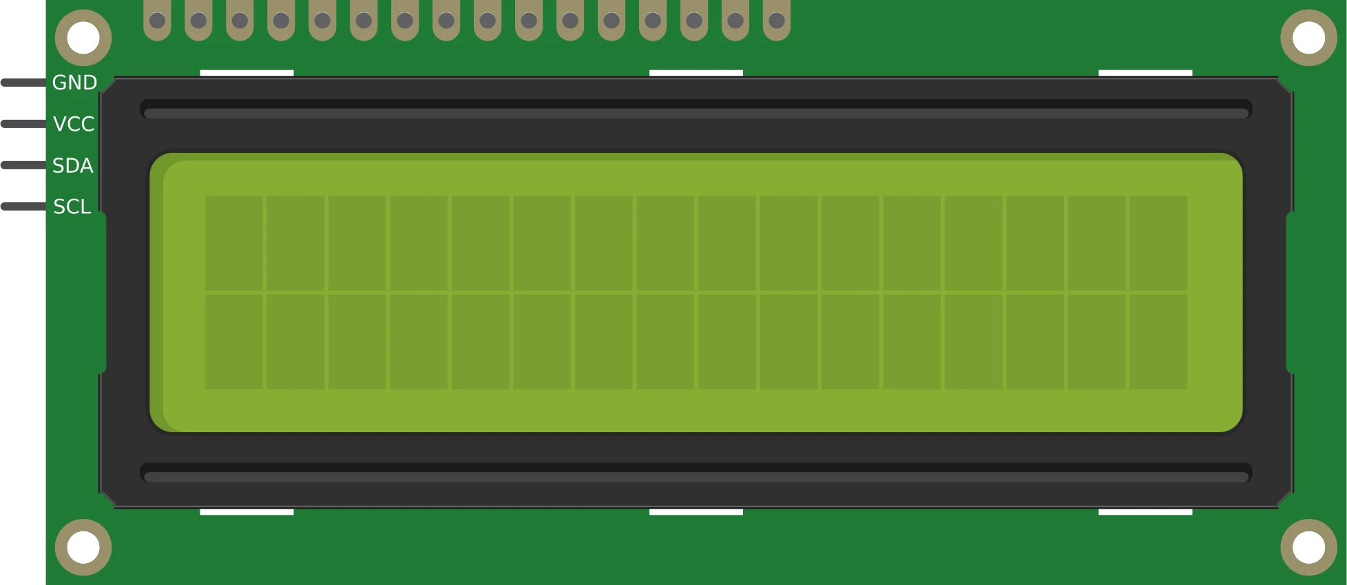
lcd-1602-parallel16×2 character display
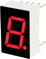
7seg-displaySingle numeric digit
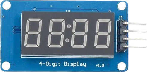
tm1637-4digit-displayFour-digit segment module
Drop the MAX7219 LED Matrix into a circuit, write firmware, and simulate it in your browser, then deploy to real hardware. All in one editable Tinkered project.