Contactless knob or throttle
Replace a wearing potentiometer with an AS5600 and a magnet on the knob shaft for a smooth, endless-life analog or I2C dial.
12-bit contactless magnetic rotary encoder that reads absolute shaft angle from a diametric magnet over I2C, analog, or PWM.
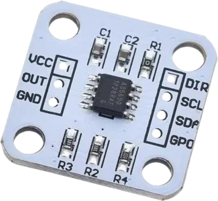
The AS5600 from ams is a programmable contactless position sensor that measures the absolute angle of a diametrically magnetized magnet placed on the rotation axis. An on-chip Hall sensor array plus CORDIC angle processing resolves a full turn into 12 bits (4096 positions per revolution, about 0.088 degrees per step). Because nothing touches the shaft, there is no mechanical wear, which is the main reason it replaces a resistive potentiometer in a rotary sensing role.
It reports angle three ways from a single device. Over I2C it answers at address 0x36 (clock up to 1 MHz), on the OUT pin it can drive a ratiometric analog voltage that scales from 0 to VDD, or that same OUT pin can emit a PWM-encoded angle. By default the output covers a full 0 to 360 degrees, but you can program a reduced arc by setting a zero (start) position and a maximum (stop) position, with the usable angular range configurable from 18 degrees up to 360 degrees. The DIR pin selects whether values increase for clockwise or counterclockwise rotation.
Non-volatile configuration is burned through the I2C interface itself, so no dedicated programmer is needed, and built-in automatic gain control and magnet detection help you position the magnet correctly. The part runs from either 3.3V or 5V and includes automatic low-power modes. Typical uses include contactless potentiometers and knobs, pedals, RC servos, brushless motor commutation, and robot joint feedback.
| Pin | Function | Type |
|---|---|---|
VCC VCC (3.3-5V) | Power | Power in |
OUT OUT | Analog ratiometric angle (0–VDD) · PWM PWM-encoded angle | Digital output |
GND GND | Power | Power in |
DIR DIR | Digital rotation polarity: GND = CW increases, VDD = CCW increases | Digital input |
SCL SCL | I²C SCL (I²C clock, up to 1 MHz) | Digital input |
SDA SDA | I²C SDA (I²C data, addr 0x36) | Bidirectional (GPIO) |
GPO GPO (PGO) | Digital program option (PGO): pull to GND for OTP burn / Option B | Bidirectional (GPIO) |
Verified from the Tinkered component library · ams (AS5600).
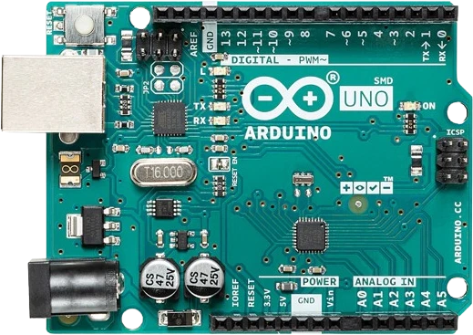
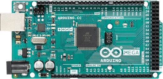
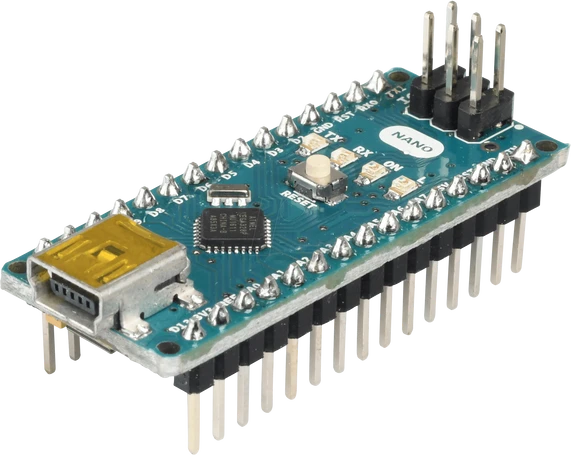
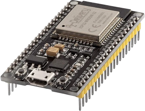
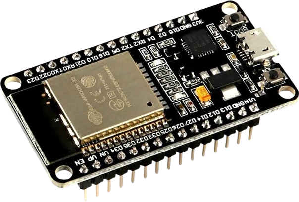
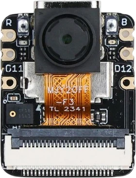
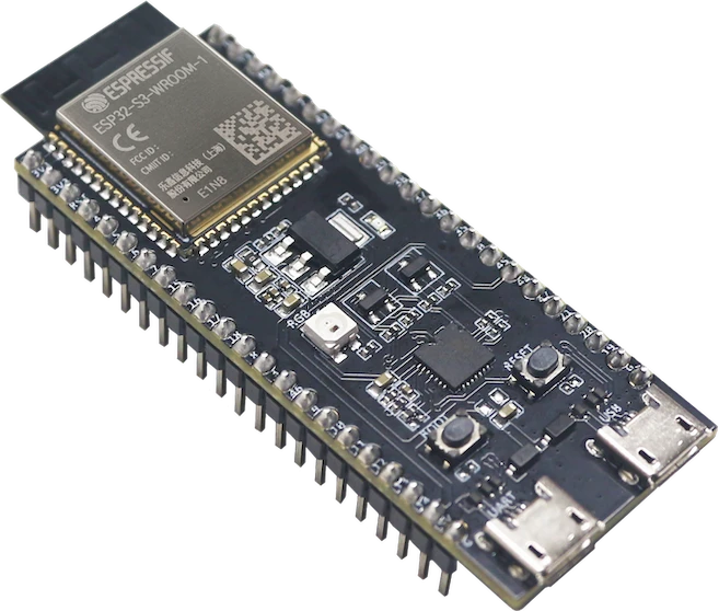
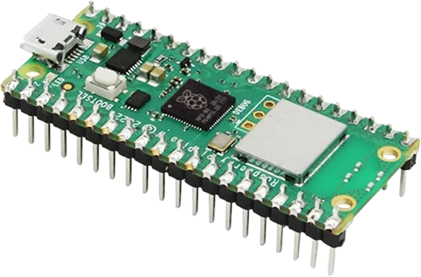
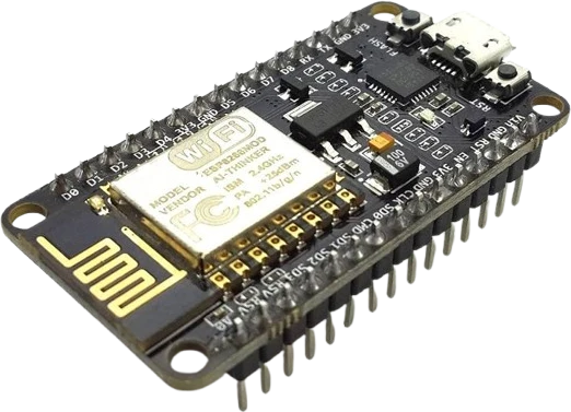
The AS5600 connects to any of the microcontrollers supported in Tinkered. Mind the 3.3 V logic level on 3.3 V boards.
The AS5600 is fully simulated in Tinkered. Wire it into a circuit, write your firmware, and read real values back with no physical hardware. Test your logic before you touch a breadboard.
Open it in the simulatorThe AS5600 only tracks a two-pole diametrically magnetized magnet. An axially or radially magnetized magnet, or a random fridge magnet, produces meaningless angle values even though the sensor still powers up and answers on I2C.
The magnet must sit centered on the axis over the die and stay parallel to the package. Even a small lateral offset or tilt causes nonlinearity, noise, and sudden jumps in the reported angle.
Placing the magnet too far weakens the field (ML flag) and too close saturates it (MH flag). Skipping the magnet detection and AGC checks leaves readings noisy, clipped, or stuck.
If a start/stop position or maximum angle has been programmed, the scaled ANGLE register only covers that reduced arc. Read the RAW ANGLE register when you want the full unscaled 0-4095 output.
Configuration and angle settings can only be permanently burned into OTP a limited number of times, and the operation is irreversible. Verify everything with volatile register writes before ever issuing a burn command.
Replace a wearing potentiometer with an AS5600 and a magnet on the knob shaft for a smooth, endless-life analog or I2C dial.
Feed absolute shaft angle to a field-oriented control library such as SimpleFOC for closed-loop control of gimbal and BLDC motors.
Sense joint or arm rotation without slip rings or contact wear, giving servos and robotic joints reliable absolute position.
Build a tuning dial, jog wheel, or steering input that reports precise angle to an Arduino over I2C.
Drop the AS5600 into a circuit, write firmware, and simulate it in your browser, then deploy to real hardware. All in one editable Tinkered project.