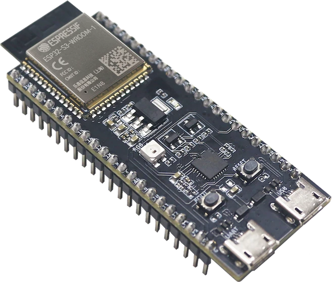
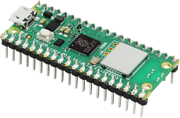
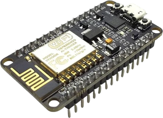
Digital alarm clock
Combine the DS3231's two programmable alarms and SQW interrupt with an LCD or OLED display to build a clock that keeps accurate time and wakes the microcontroller on schedule.
The DS3231 is an I2C real-time clock whose integrated temperature-compensated crystal oscillator (TCXO) holds time to within about a minute a year.
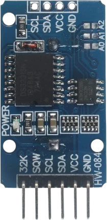
The DS3231 is a low-cost, extremely accurate I2C real-time clock (RTC) from Analog Devices (formerly Maxim/Dallas). It tracks seconds, minutes, hours, day-of-week, date, month, and year, and automatically handles months shorter than 31 days and leap years. What sets it apart from cheaper clocks like the DS1307 is its integrated TCXO and crystal: the chip continuously measures its own temperature and corrects the oscillator, giving an accuracy of plus or minus 2ppm from 0 to +40C (roughly plus or minus 1 minute per year) and plus or minus 3.5ppm across the full -40 to +85C range.
A dedicated VBAT input lets the DS3231 keep running from a backup coin cell when main power is removed, so the clock does not lose time between power cycles. The device also provides two programmable time-of-day alarms, a programmable square-wave / interrupt output (SQW) at 1Hz, 1.024kHz, 4.096kHz, or 8.192kHz, a separate 32.768kHz output, and an on-chip temperature sensor (0.25C resolution) readable over I2C. All time and calendar registers are stored in binary-coded decimal (BCD).
On the common breakout module the DS3231 sits at fixed I2C address 0x68 and includes on-board SDA/SCL pull-up resistors, so it drops onto an Arduino or ESP with just VCC, GND, SDA, and SCL. The verified specs list a 3.3 to 5.5V supply, and the same SDA/SCL lines work with both 3.3V and 5V logic. Many of these modules also bundle an AT24C32 EEPROM on the same bus for extra non-volatile storage.
| Pin | Function | Type |
|---|---|---|
32K 32K | Digital 32.768 kHz output | Digital output |
SQW SQW | Digital interrupt / square-wave output | Digital output |
SCL SCL | I²C SCL | Bidirectional (GPIO) |
SDA SDA | I²C SDA | Bidirectional (GPIO) |
VCC VCC | Power | Power in |
GND GND | Power | Power in |
Verified from the Tinkered component library · Analog Devices / generic breakout module.
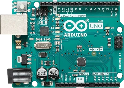
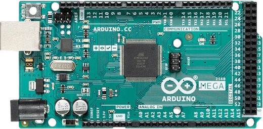
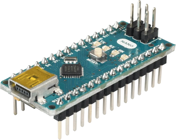
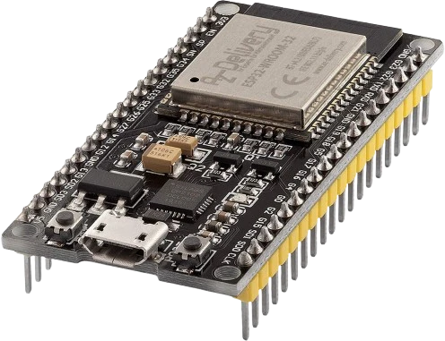
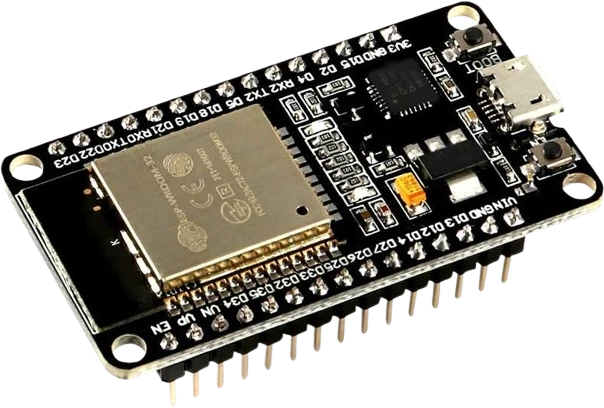
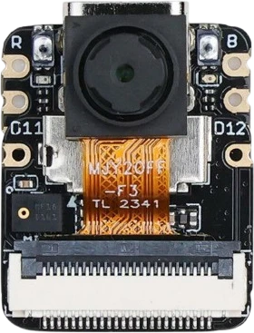
The DS3231 RTC connects to any of the microcontrollers supported in Tinkered. Mind the 3.3 V logic level on 3.3 V boards.
The popular ZS-042 style module includes a trickle-charge circuit (a resistor plus diode) intended for a rechargeable LIR2032. Fitting a standard non-rechargeable CR2032 means the board tries to charge a cell that cannot be charged, which can cause it to leak, overheat, or vent. Use a LIR2032, or remove/disable the charging resistor before using a CR2032.
The DS3231 lives at 0x68, the same default address as the MPU-6050 IMU. Wiring both to one I2C bus produces bus conflicts and garbage reads. Run an I2C scanner first and re-address or separate the conflicting device.
Example sketches often call a set-time function that writes the compile-time timestamp. If that line is left in the main loop or run unconditionally at startup, the clock is overwritten to the same stale time on every reset. Set the time once, then comment out or guard that call so the RTC keeps its own count.
The on-chip temperature sensor updates its conversion roughly every 64 seconds by default, not continuously. Reading the temperature register in a tight loop returns the same value until the next conversion; force a conversion via the control register if you need it sooner.
Time and date registers are stored in binary-coded decimal, not plain binary. Reading a register directly without BCD-to-decimal conversion yields nonsense values (for example 0x59 instead of 59). Use a maintained RTC library, or convert explicitly.
Combine the DS3231's two programmable alarms and SQW interrupt with an LCD or OLED display to build a clock that keeps accurate time and wakes the microcontroller on schedule.
Pair the RTC with an SD card or the on-module EEPROM to tag sensor readings with the exact date and time, keeping records aligned even across power outages.
Use the alarms to trigger relays or pumps at set times for tasks like plant watering, aquarium lighting, or feeding, running independently of any network time source.
Drive a microcontroller's interrupt pin from SQW/INT so the board sleeps and wakes only at programmed intervals, extending battery life on remote monitoring projects.
Drop the DS3231 RTC into a circuit, write firmware, and simulate it in your browser, then deploy to real hardware. All in one editable Tinkered project.