Self-balancing robot
Fuse the accelerometer and gyroscope to estimate tilt in real time and drive the motors that keep a two-wheeled robot upright.
6-axis MotionTracking sensor that combines a 3-axis gyroscope and 3-axis accelerometer on one I2C chip, with an on-chip Digital Motion Processor for offloaded sensor fusion.
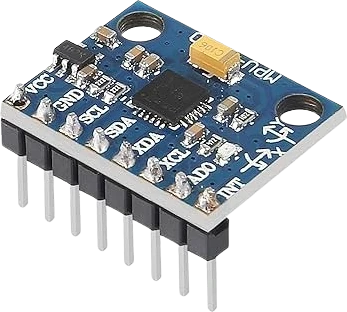
The MPU-6050 (InvenSense, now TDK) is a 6-axis inertial measurement unit that integrates a 3-axis gyroscope and a 3-axis accelerometer on a single die. Each of the six channels is digitized by its own 16-bit ADC, so the part streams true digital values rather than analog voltages. The gyroscope has a user-programmable full-scale range of plus or minus 250, 500, 1000, and 2000 degrees per second, and the accelerometer is configurable to plus or minus 2, 4, 8, and 16 g. An on-chip temperature sensor is included as well, and all of it is read over I2C at clock speeds up to 400 kHz.
On common breakout boards (the GY-521 is the usual one), the chip is broken out to 8 pins with an onboard voltage regulator and I2C pull-up resistors. The regulator lets the VCC pin accept a 3.3-5V supply, which is why the module drops onto both 3.3V and 5V microcontrollers, even though the bare MPU-6050 die itself runs at 3.3V. The default I2C address is 0x68, and pulling the AD0 pin high changes it to 0x69, so two of these can share one bus. An embedded Digital Motion Processor (DMP) and a 1024-byte FIFO can buffer and pre-process motion data to reduce host-processor load.
The device also exposes an auxiliary I2C master bus on the XDA and XCL pins. Connecting an external magnetometer to this bus lets the MPU-6050 gather a full 9-axis dataset for MotionFusion without extra work from the main processor. A dedicated INT (interrupt) pin can signal data-ready, motion-detection, and FIFO events so the host does not have to poll continuously.
| Pin | Function | Type |
|---|---|---|
VCC VCC (3.3-5V) | Power | Power in |
GND GND | Power | Power in |
SCL SCL | I²C SCL | Bidirectional (GPIO) |
SDA SDA | I²C SDA | Bidirectional (GPIO) |
XDA XDA (Aux) | I²C SDA | Bidirectional (GPIO) |
XCL XCL (Aux) | I²C SCL | Bidirectional (GPIO) |
AD0 AD0 (Addr) | Digital | Digital input |
INT INT | Digital | Digital output |
Verified from the Tinkered component library.
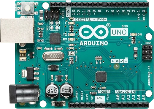
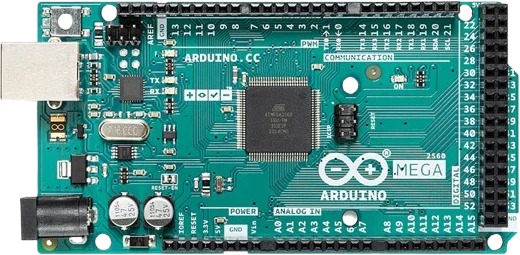
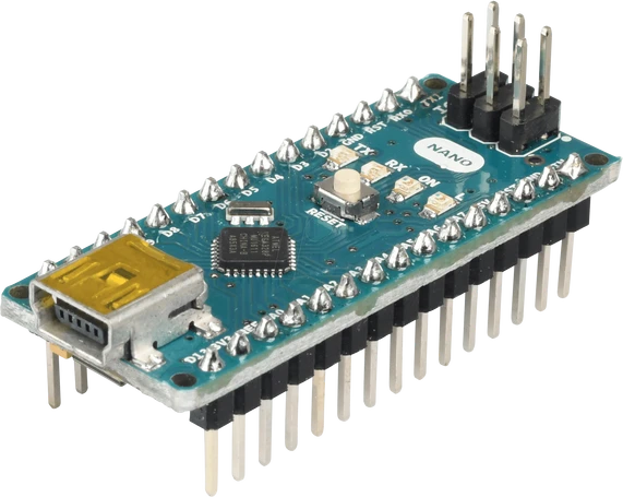
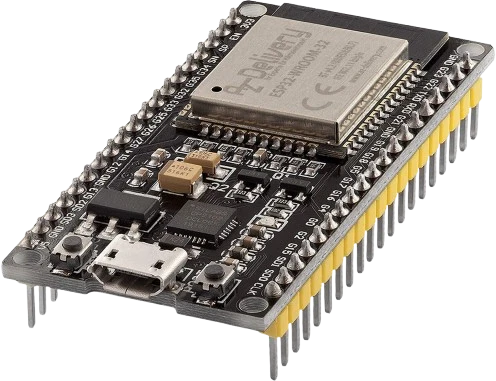
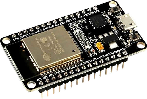
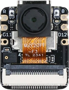
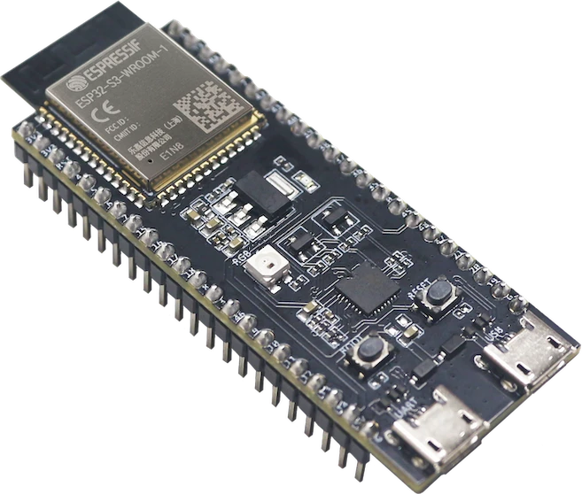
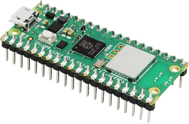
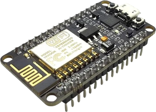
The MPU6050 connects to any of the microcontrollers supported in Tinkered. Mind the 3.3 V logic level on 3.3 V boards.
The MPU6050 is fully simulated in Tinkered. Wire it into a circuit, write your firmware, and read real values back with no physical hardware. Test your logic before you touch a breadboard.
Open it in the simulatorThe MPU-6050 boots into sleep mode. If you get all-zero or frozen readings, you likely never cleared the SLEEP bit in the PWR_MGMT_1 register (0x6B). Most libraries do this in their begin()/initialize() call, so calling that first is essential.
An unconnected AD0 pin lets the I2C address drift between 0x68 and 0x69, causing intermittent 'device not found' errors. Tie AD0 to GND for 0x68 or to VCC/3.3V for 0x69, especially when two units share the bus.
The accelerometer and gyroscope output raw acceleration and angular-rate values, not tilt or heading. Usable orientation requires fusing the two (complementary or Kalman filter) or using the on-chip DMP; raw gyro integration alone drifts over time.
It is the breakout board's regulator that tolerates 5V, not the MPU-6050 itself. Wiring 5V directly to the sensor die's VDD (on a custom board without a regulator) exceeds its rating and can destroy it.
Every unit has a small zero-rate bias, so a stationary sensor still reports a nonzero rotation that accumulates into angle drift. Averaging a few hundred samples while the board sits still and subtracting that offset greatly improves results.
Fuse the accelerometer and gyroscope to estimate tilt in real time and drive the motors that keep a two-wheeled robot upright.
Use the six axes as the core attitude sensor in a flight-stabilization loop, taking advantage of the high-rate gyro and selectable ranges.
Read gravity direction from the accelerometer to build a tilt meter or electronic spirit level with degree readouts.
Detect taps, shakes, and free-fall using the INT pin and motion thresholds to trigger actions without polling.
Track head or controller orientation for immersive interfaces, optionally adding a magnetometer on the auxiliary bus for 9-axis heading.
Drop the MPU6050 into a circuit, write firmware, and simulate it in your browser, then deploy to real hardware. All in one editable Tinkered project.