Robot obstacle avoidance
Mount one or several VL53L0X sensors as forward or side range finders for wall following and collision avoidance, using reflectance-independent readings that beat simple IR proximity modules.
A laser time-of-flight distance sensor that measures absolute range up to 2 m over I2C, independent of the target's color or reflectance.
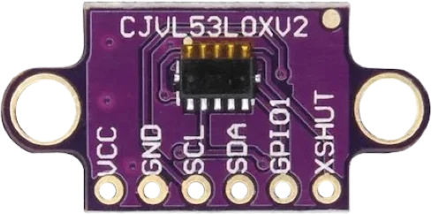
The VL53L0X is ST's second-generation FlightSense time-of-flight (ToF) ranging module. Instead of estimating distance from reflected light intensity like an IR proximity sensor, it emits invisible 940 nm laser pulses from a VCSEL and times how long the photons take to return to an on-chip array of Single Photon Avalanche Diodes (SPADs). Because it measures elapsed time rather than brightness, the reported distance stays accurate whether the target is white, black, matte, or glossy.
An embedded microcontroller runs the whole ranging pipeline and exposes results over I2C, so the host only reads a distance in millimeters. The device measures absolute range up to about 2 m with a field of view near 25 degrees, and it is eye-safe (Class 1 laser per IEC 60825-1:2014). Ranging behavior is configurable through timing budget and profiles: the default profile is tuned for speed at shorter range, while long-range and high-accuracy profiles trade measurement rate for reach or precision.
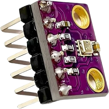
On this GY/CJMCU-style breakout the bare ST silicon sits behind an onboard voltage regulator and I2C pull-ups, so the board runs from a 3.3-5V supply. Two extra pins expose the sensor's control lines: XSHUT for hardware shutdown/reset, and GPIO1 as a programmable interrupt output for data-ready or threshold events.
| Pin | Function | Type |
|---|---|---|
VCC VCC (3-5V) | Power | Power in |
GND GND | Power | Power in |
SCL SCL | I²C SCL | Bidirectional (GPIO) |
SDA SDA | I²C SDA | Bidirectional (GPIO) |
GPIO1 GPIO1 (INT) | Digital interrupt output (open-drain) | Digital output |
XSHUT XSHUT | Digital shutdown / reset, active LOW | Digital input |
Verified from the Tinkered component library · GY / CJMCU breakout (ST VL53L0X).
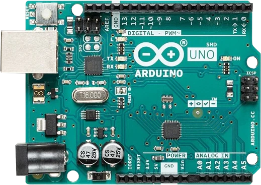
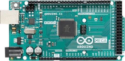
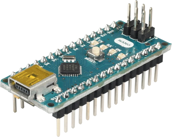
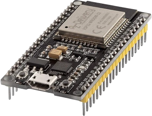
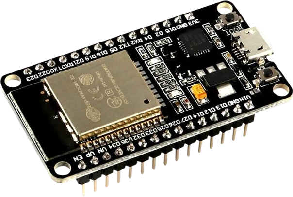
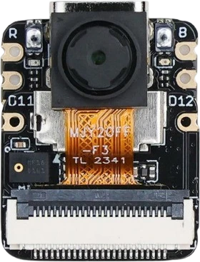
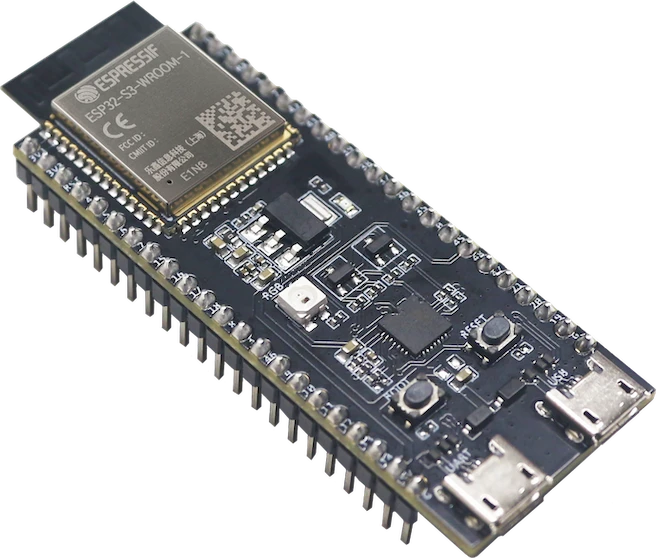
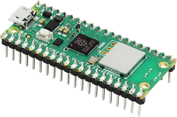
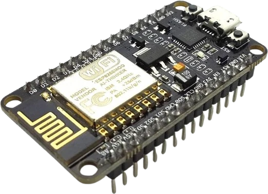
The VL53L0X ToF connects to any of the microcontrollers supported in Tinkered. Mind the 3.3 V logic level on 3.3 V boards.
The 3.3-5V rating belongs to the breakout's regulator, not the sensor die. The VL53L0X silicon operates at 2.6-3.5V and its pins are not 5V tolerant. Only the regulated breakout accepts 5V on VCC.
All VL53L0X units power up at address 0x29, so a second one causes an address clash. You must use XSHUT to enable them one at a time and reprogram addresses, and repeat that after every reset because the new address does not persist.
The datasheet lists 0x52 (8-bit), while most Arduino and Python libraries expect the 7-bit form 0x29. Passing the wrong one means the sensor never ACKs and scans come up empty.
The default ranging profile is optimized for speed and tops out around 1.2 m. Reaching close to 2 m requires the long-range profile, low ambient light, and a reasonably reflective target.
With XSHUT unconnected the sensor may not boot or run reliably. Tie it high for single-sensor use, or drive it from a GPIO when you need shutdown control or multi-sensor addressing.
Mount one or several VL53L0X sensors as forward or side range finders for wall following and collision avoidance, using reflectance-independent readings that beat simple IR proximity modules.
Detect a hand entering the sensor's cone and fire an interrupt on GPIO1 to trigger a pump or valve, the classic 'hand detection' use case ST designed FlightSense for.
Read changing distance over time to recognize hand swipes and hover gestures for a contactless dimmer, volume knob, or menu scroller.
Aim the sensor down into a container and convert measured distance to fill level for water tanks, feed hoppers, or waste bins, then log or alert over I2C.
Use the sensor to detect a user approaching a display or laptop and wake it, saving power while people are away.
Drop the VL53L0X ToF into a circuit, write firmware, and simulate it in your browser, then deploy to real hardware. All in one editable Tinkered project.