Red LED
A 5mm through-hole red LED: a polarized indicator that emits around 625nm and drops about 2V at its 20mA rated current.

What is the Red LED?
The red LED is a 5mm (T-1 3/4) through-hole light-emitting diode, one of the most common indicator parts in hobby electronics. It emits red light near the 620-630nm range and, like any diode, conducts in only one direction, so it must be wired with the correct polarity to light up.
The part has two leads: the anode (+) and the cathode (-). The anode is usually the longer lead, and the cathode is identified by the shorter lead plus a flat notch molded into the round plastic body. Conventional current flows from anode to cathode, and reversing the connection simply leaves the LED dark.
At its 20mA rated forward current a red LED drops roughly 2.0V, which is lower than blue or white LEDs. Because a diode's current rises steeply once it passes its forward voltage, the LED always needs a series current-limiting resistor between it and the supply rather than a bare connection across the rail.
Specifications
- Forward voltage
- 2 V
- Dimensions
- 5 × 8.6 × 5 mm
Verified from the Tinkered component library.
Circuit requirements
- Always place a series current-limiting resistor between the LED and the supply. Never connect the LED directly across a voltage source.
- Size the resistor as R = (Vsupply - 2.0V) / I. On a 5V Arduino pin targeting 20mA that is about 150 ohm; a common 220 ohm resistor gives a safe and still-bright ~14mA.
- Observe polarity: the anode (+) goes toward the more positive side (the driving pin or supply), and the cathode (-) goes toward ground or the lower potential.
- Keep DC forward current at or below the roughly 30mA absolute maximum. The 20mA rating is the practical sweet spot for brightness and lifespan.
- The reverse voltage rating is low (about 5V), so avoid reverse-biasing the LED beyond that; it is not a rectifier diode.
Board compatibility
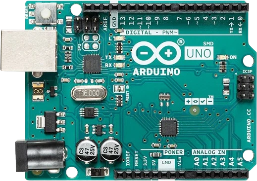
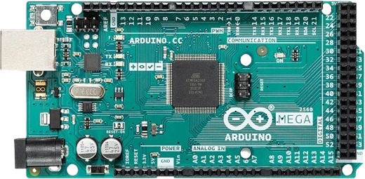
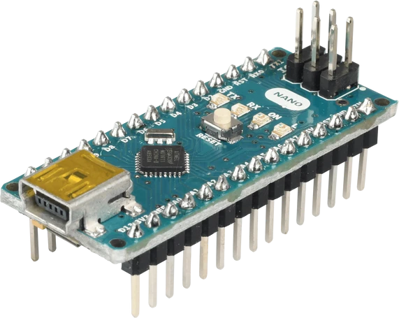
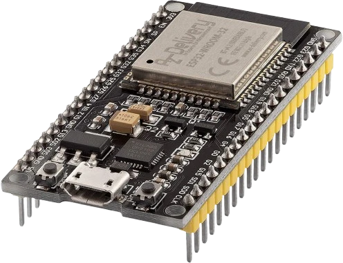
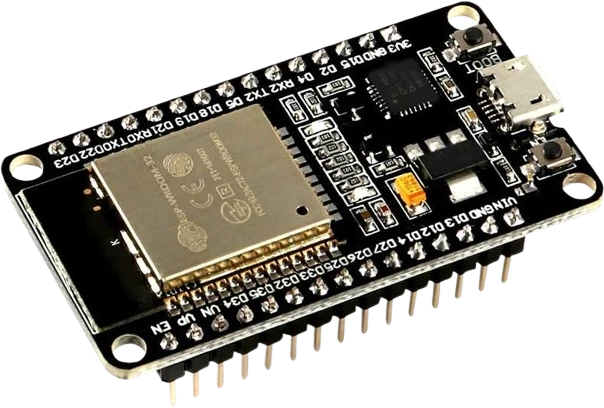
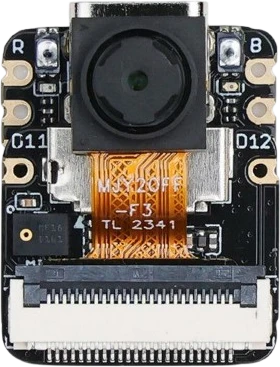
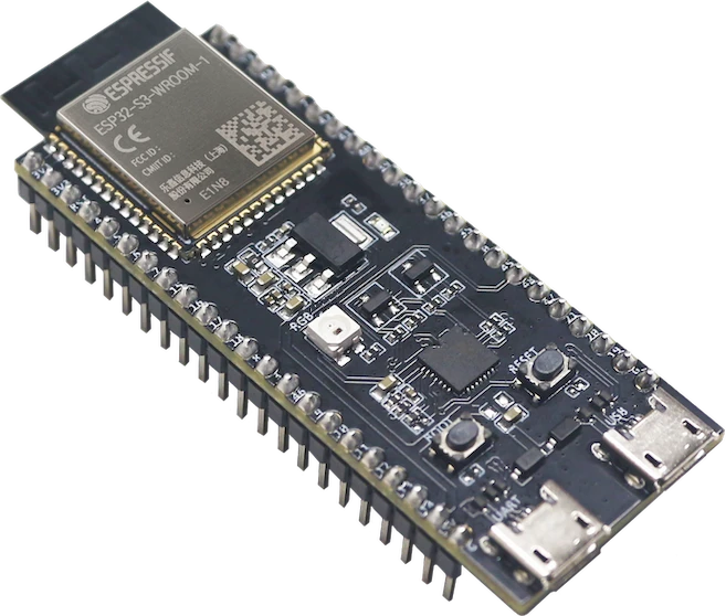
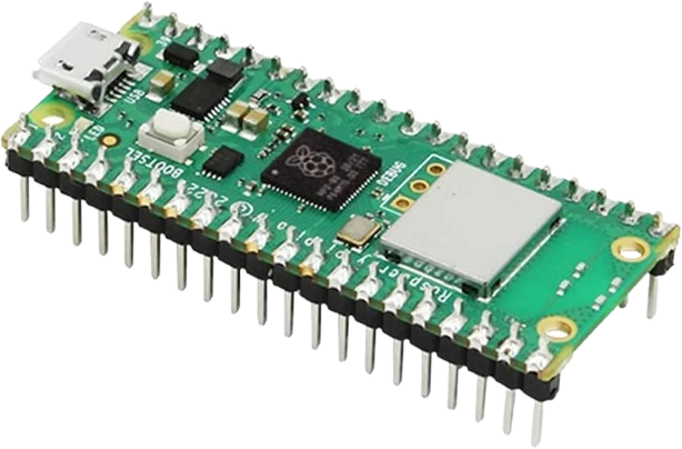
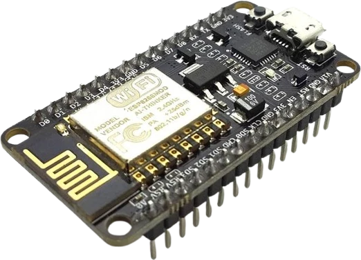
The Red LED connects to any of the microcontrollers supported in Tinkered.
Common Red LED mistakes
Wiring the LED backwards
The LED is polarized and only conducts from anode to cathode. If it stays dark, the leads are likely reversed. Find the cathode by the shorter lead and the flat notch on the body.
Omitting the series resistor
Connecting the LED directly to 5V (or any rail) with no current-limiting resistor lets it draw far more than 20mA and burns it out almost instantly. A resistor is mandatory, not optional.
Reusing the red 2V drop for other colors
Blue, white, and green LEDs have higher forward voltages (often 3.0-3.4V). Plugging red's ~2.0V into the resistor formula for those colors gives the wrong current, so always use the target LED's own forward voltage.
Sharing one resistor across parallel LEDs
Two LEDs in parallel behind a single resistor rarely split current evenly. Small differences in forward voltage let one LED hog the current and run brighter or hotter. Give each LED its own series resistor.
Exceeding the reverse voltage rating
Unlike a rectifier diode, a red LED's reverse breakdown is only about 5V. Applying larger reverse voltage (for example across an AC source without protection) can damage it.
More leds & addressable




Build with the Red LED.
Drop the Red LED into a circuit, write firmware, and simulate it in your browser, then deploy to real hardware. All in one editable Tinkered project.