Circular status indicator
Map a value like battery level, progress, or signal strength onto the 12 pixel positions for an at-a-glance gauge.
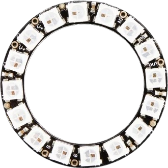
A ring of 12 individually addressable 5050 RGB LEDs driven from a single 5V data wire.
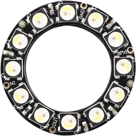
The NeoPixel Ring 12 (Adafruit product 1643) packs 12 individually addressable RGB LEDs into a 36.8mm round PCB. Each 5050 LED has its own tiny driver chip built in, so the whole ring is controlled from one microcontroller pin instead of 36 separate connections. Boards ship with either WS2812B or SK6812 LEDs, which share the same brightness, color, and single-wire protocol.
Pixels are addressed over one data line using a timing-based protocol at roughly 800 KHz. Each pixel reads the first 24 bits of the incoming stream as its own color (8 bits each of red, green, and blue, for about 16.7 million colors), then passes the remaining data out its DOUT pin to the next pixel's DIN. Because of this, the data stream only ever flows one direction around the ring. An 8 MHz or faster processor is needed to generate the timing.
The ring runs on 5V. Adafruit rates each pixel channel at about 18mA constant-current drive, and a single pixel can pull up to roughly 60mA at full-brightness white, so all 12 lit white can approach 720mA. Multiple rings chain together by wiring the DOUT of one into the DIN of the next.
| Pin | Function | Type |
|---|---|---|
VCC +5V | Power | Power in |
GND GND | Power | Power in |
DIN DIN | Digital · 1-Wire WS2812 | Digital input |
DOUT DOUT | Digital · 1-Wire WS2812 | Free |
Verified from the Tinkered component library · Adafruit.
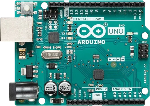
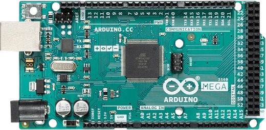
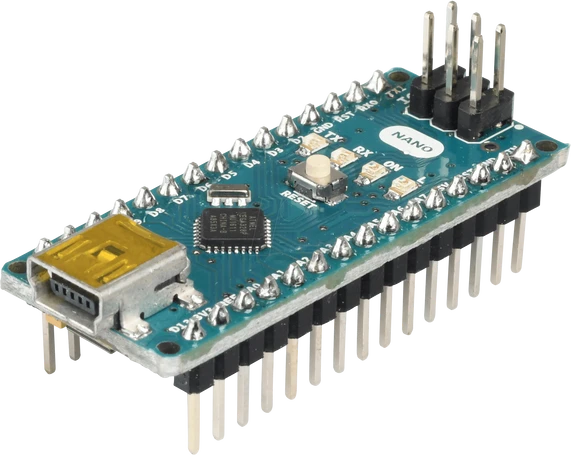
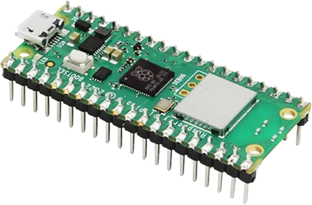
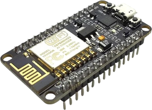
The NeoPixel Ring 12 connects to any of the microcontrollers supported in Tinkered. Mind the 5 V logic level on 3.3 V boards.
The NeoPixel Ring 12 is fully simulated in Tinkered. Wire it into a circuit, write your firmware, and read real values back with no physical hardware. Test your logic before you touch a breadboard.
Open it in the simulatorData only flows DIN to DOUT. Connecting the microcontroller to the output end leaves the ring dark. Always drive DIN, and follow the arrow when chaining.
5V pixels driven directly by 3.3V logic often flicker or show wrong colors, especially the first pixel. Add a 74AHCT125 or similar buffer to raise the data line to 5V.
Twelve pixels at full white can draw around 720mA, well beyond what a board's onboard regulator can supply. This causes brownouts and resets. Use an external 5V supply.
Without the ~1000uF bulk capacitor and the 300-500 ohm data resistor, inrush spikes and data ringing can corrupt the stream or damage the first pixel on power-up.
When the ring is powered from a separate supply, its ground must connect to the microcontroller ground. Otherwise the data signal has no shared reference and colors come out wrong.
Map a value like battery level, progress, or signal strength onto the 12 pixel positions for an at-a-glance gauge.
Drive the ring from a sound or FFT reading so it pulses and spins in time with music.
Use the 12 pixels as hour marks or a sweeping countdown, with color encoding minutes or seconds.
Flash or breathe a color to signal new messages, alerts, or system states in a desk or wearable build.
Cycle a smooth rainbow around the ring for an ambient light that shows off the full 24-bit color range.
Drop the NeoPixel Ring 12 into a circuit, write firmware, and simulate it in your browser, then deploy to real hardware. All in one editable Tinkered project.