Yellow LED
A 5mm (T-1 3/4) through-hole yellow indicator LED with a forward drop near 2V, built on GaAsP/GaP and emitting around 585-590nm.

What is the Yellow LED?
The yellow LED is a single-color, diffused 5mm (T-1 3/4) light-emitting diode used as a status or indicator light. Like every LED it is a polarized two-terminal device: current enters at the anode (+) and exits at the cathode (-), and it only lights when biased in the forward direction. Its yellow output sits around 585-590nm, produced by GaAsP/GaP semiconductor material.
Because it is a diode, an LED is current-driven rather than voltage-driven. Once the forward voltage (roughly 2V for yellow) is reached, current climbs very steeply for tiny voltage increases, so the current must be set externally rather than by the supply alone. Brightness tracks that current up to the part's rated maximum, typically about 20mA for a standard 5mm lamp.
The package measures about 5mm in diameter and 8.6mm tall. Out of the bag the longer lead is the anode and the shorter lead is the cathode; the cathode side is also marked by the flat notch on the base flange, which stays readable even after the leads are trimmed.
Specifications
- Forward voltage
- 2 V
- Dimensions
- 5 × 8.6 × 5 mm
Verified from the Tinkered component library.
Circuit requirements
- Always place a series current-limiting resistor in line with the LED. Wiring it directly across a supply or an output pin will let current run away and burn out the die.
- Size the resistor with R = (Vsupply - Vf) / I. With a ~2V forward drop from a 5V pin, 150 ohms targets roughly 20mA, and 220 ohms gives a safer ~13-14mA that is plenty bright for an indicator.
- From 3.3V logic the same 2V drop leaves less headroom, so a smaller resistor (around 68-100 ohms) is needed to reach a similar current.
- Keep forward current at or below the ~20mA rating; higher current adds little visible brightness and shortens life.
- Observe polarity: anode goes toward the more positive node (pin or supply through the resistor), cathode goes toward ground. Reverse voltage tolerance is small (about 5V), so do not rely on reverse bias.
Board compatibility
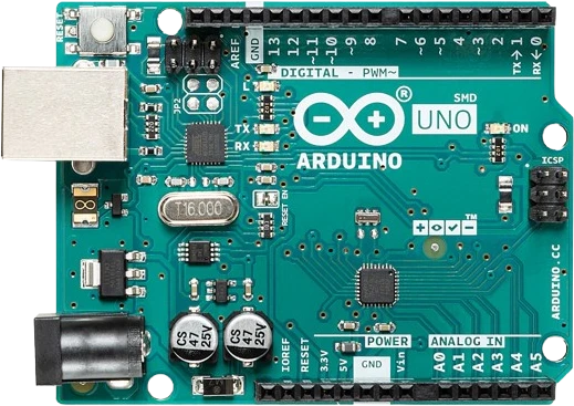
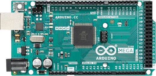
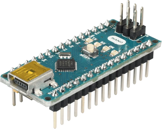
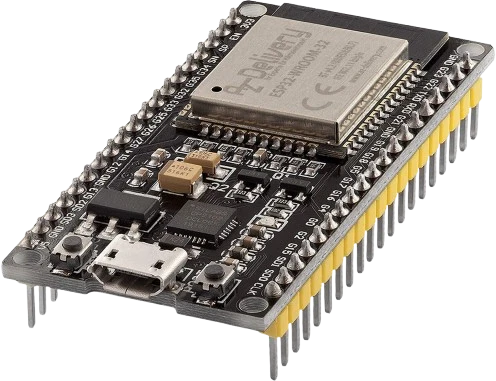
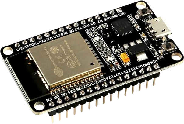
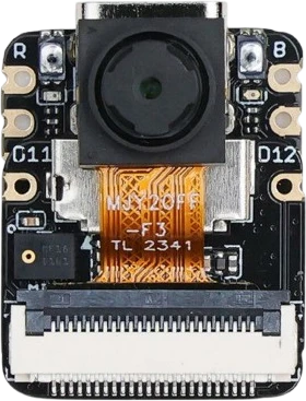
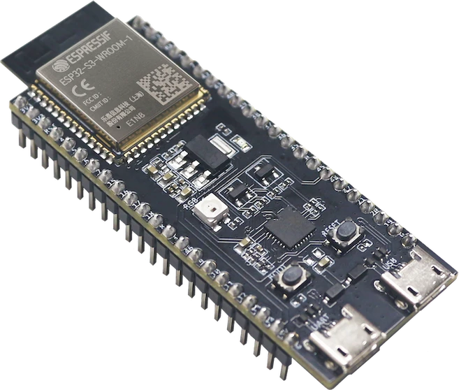
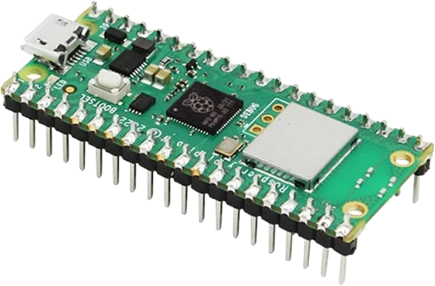
The Yellow LED connects to any of the microcontrollers supported in Tinkered.
Common Yellow LED mistakes
Leaving out the series resistor
Connecting the LED straight to 5V or an output pin draws excessive current and destroys it, often instantly. A resistor is mandatory, not optional.
Reversing anode and cathode
Wired backwards the LED simply stays dark and blocks current. Remember the long lead is the anode (+) and the flat/notched side marks the cathode (-).
Reusing a blue or white LED resistor value
Yellow drops about 2V while blue and white drop closer to 3V. Copying a resistor sized for a 3V LED pushes far more current through a yellow one, so recalculate for the lower forward voltage.
Trying to dim it by lowering supply voltage
Below the forward voltage the LED barely conducts and above it current spikes, so small voltage changes are an unstable way to set brightness. Control current with the resistor, or use PWM.
Losing the polarity marking after trimming leads
Once both legs are cut to equal length the lead-length cue is gone. Use the flat spot on the rim, which always indicates the cathode, before soldering.
More leds & addressable




Build with the Yellow LED.
Drop the Yellow LED into a circuit, write firmware, and simulate it in your browser, then deploy to real hardware. All in one editable Tinkered project.