RGB LED
A 5mm through-hole RGB LED that combines red, green, and blue emitters in one common-cathode package for full-color mixing.

What is the RGB LED?
This is a standard 5mm through-hole RGB LED: three independent LED dies (red, green, and blue) packaged in a single clear lens that share one common cathode. It has four legs, one anode for each color plus the shared cathode (the longest leg), and measures roughly 5mm in diameter by 8.6mm tall.
Each color is driven as its own analog channel. Because the three dies share only their negative terminal, you control brightness on each anode independently, and blending the channels with PWM produces a wide range of mixed colors from a single lens. There is no controller, memory, or data protocol inside the part: it behaves as three ordinary LEDs, not as an addressable pixel.
The red channel has a low forward voltage (about 2V per the verified specs), while the green and blue channels require a noticeably higher forward voltage. That difference matters when you size resistors and try to balance a neutral white.
RGB LED pinout
| Pin | Function | Type |
|---|---|---|
red Red (+) | Passive | Passive |
cathode Cathode (-) | Passive | Passive |
green Green (+) | Passive | Passive |
blue Blue (+) | Passive | Passive |
Specifications
- Forward voltage
- 2 V
- Dimensions
- 5 × 8.6 × 5 mm
Verified from the Tinkered component library.
Circuit requirements
- Common cathode: the single shared (longest) leg goes to GND. The red, green, and blue anodes are the controlled positive pins, each driven from its own output.
- Give every color channel its own series current-limiting resistor. Never share one resistor across the three anodes, or the current per color will change depending on how many channels are lit.
- Because green and blue have a higher forward voltage than red, identical resistor values yield unequal brightness. Use different resistor values per channel (or trim brightness in software with PWM) to get a balanced white.
- Drive each anode from a PWM-capable output (for example analogWrite on an Arduino) to mix intermediate colors instead of only the eight full-on/off combinations.
- This is a common-cathode part. A common-anode RGB LED is wired the opposite way (shared pin to +V, colors switched on the low side), so confirm the type before wiring.
Board compatibility
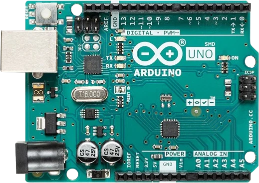
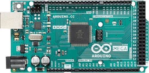
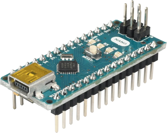
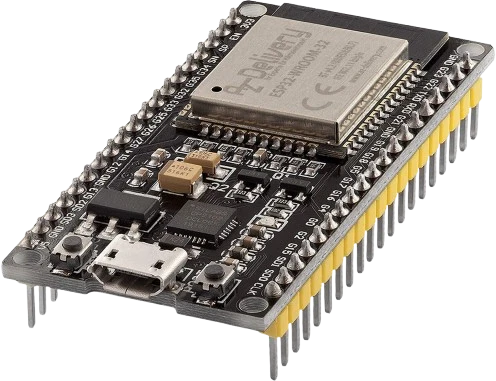
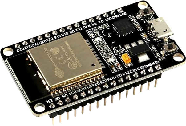
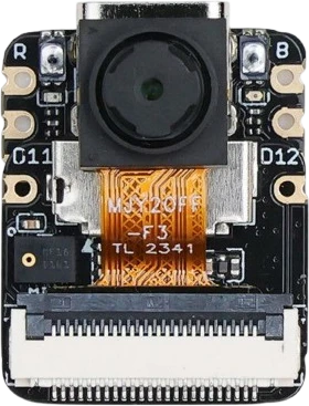
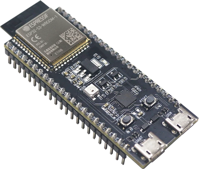
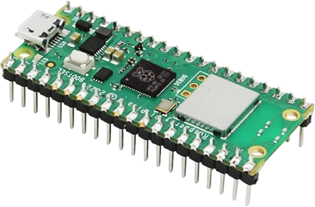
The RGB LED connects to any of the microcontrollers supported in Tinkered.
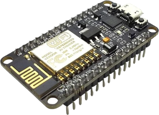
Common RGB LED mistakes
Wiring it as common anode
This part shares a common cathode, so the long leg goes to GND and the three color legs are the positive drive pins. Tying the shared leg to +5V (as you would with a common-anode LED) leaves it dark or backwards.
Using a single shared resistor
Putting one resistor on the common cathode instead of one resistor per anode makes each color's current depend on how many channels are on, so brightness shifts as colors mix. Use three separate resistors, one per color.
Expecting equal brightness from equal resistors
Red has a lower forward voltage and higher efficiency than green and blue, so equal resistors make pure white look tinted toward red. Balance the channels with different resistor values or PWM levels.
Swapping the color legs
The longest leg is the common cathode; the remaining three legs are red, green, and blue in a fixed datasheet order. Guessing the order gives the wrong colors. Verify the pinout before soldering.
Treating it like a NeoPixel
There is no data line, controller, or addressing here. Each color is a plain analog channel driven through a resistor, so single-wire pixel code and 5V data timing do not apply.
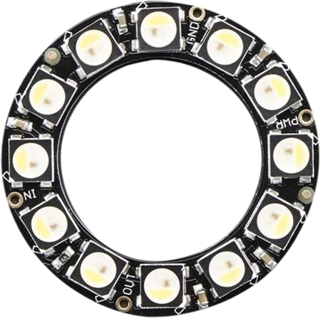
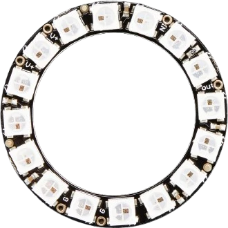
More leds & addressable




Build with the RGB LED.
Drop the RGB LED into a circuit, write firmware, and simulate it in your browser, then deploy to real hardware. All in one editable Tinkered project.