Circular status dial or gauge
Map a sensor reading, progress value, or timer onto the 24 pixels to make an animated ring gauge or countdown display.
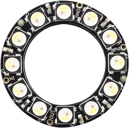
A 65.5mm Adafruit ring of 24 individually addressable WS2812/SK6812 RGB LEDs driven over a single 5V data line.
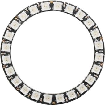
The NeoPixel Ring 24 is a circular PCB carrying 24 individually addressable RGB LEDs (it ships with WS2812B or SK6812 pixels). Every pixel has its own integrated driver chip, so one microcontroller data pin controls the color and brightness of all 24 LEDs independently across the 65.5mm ring.
All pixels share one data line using the WS2812 one-wire protocol. A frame enters at DIN, each pixel latches its own 24-bit color value, and the remaining data passes out DOUT to the next pixel's DIN. Rings chain the same way, DOUT to DIN, so several can run from a single pin. The part is powered from 5V and expects 5V logic on the data line, and the driving microcontroller needs to run at 8MHz or faster to meet the protocol timing.
Each pixel can draw up to about 60mA at full-brightness white, so a fully lit ring can pull roughly 1.44A at 5V. Plan the 5V supply around that figure rather than relying on an Arduino's onboard regulator, which can only feed a few pixels at reduced brightness.
| Pin | Function | Type |
|---|---|---|
VCC +5V | Power | Power in |
GND GND | Power | Power in |
DIN DIN | Digital · 1-Wire WS2812 | Digital input |
DOUT DOUT | Digital · 1-Wire WS2812 | Free |
Verified from the Tinkered component library · Adafruit.
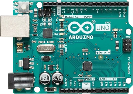
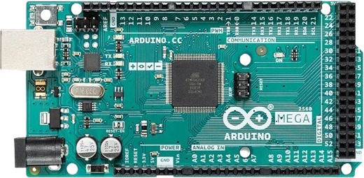
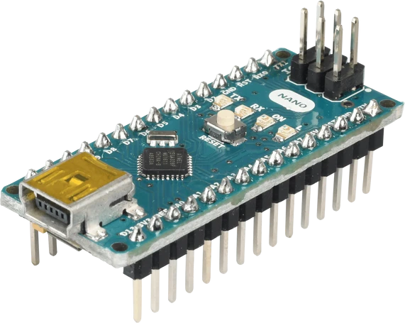
The NeoPixel Ring 24 connects to any of the microcontrollers supported in Tinkered. Mind the 5 V logic level on 3.3 V boards.
The NeoPixel Ring 24 is fully simulated in Tinkered. Wire it into a circuit, write your firmware, and read real values back with no physical hardware. Test your logic before you touch a breadboard.
Open it in the simulatorData must enter the DIN pad. DOUT is an output that only chains to the next ring. Follow the direction arrow printed on the board, and the ring stays dark or shows garbage if the two are swapped.
Skipping the 300-500 ohm series resistor on the data line and the 500-1000 uF bulk capacitor across the power rails can damage the first pixel or cause flicker, especially at the moment power is applied.
A fully lit ring can draw about 1.44A, far more than an Arduino's onboard regulator can supply. Use a dedicated 5V source sized for the pixel count and brightness.
WS2812 data expects a logic-high near 5V. A raw 3.3V signal is marginal and often unreliable. Add a 74AHCT125 or 74HCT245 level shifter between a 3.3V board and DIN.
Connect ground first, then +5V, then data, and apply pixel power before the microcontroller. Feeding data into an unpowered ring can parasitically power the pixels through DIN and stress the chips.
Map a sensor reading, progress value, or timer onto the 24 pixels to make an animated ring gauge or countdown display.
The compact ring form factor and single-wire control make it a common choice for badges, props, and costume accents animated from a small microcontroller.
Feed an audio or FFT level into the ring so the pixels pulse and sweep in time with sound as a reactive visualizer.
Use the 24 evenly spaced pixels to show hours, minutes, and seconds as colored markers around a NeoPixel clock face.
Drop the NeoPixel Ring 24 into a circuit, write firmware, and simulate it in your browser, then deploy to real hardware. All in one editable Tinkered project.